Chapter 1. Networking Introduction
“Guilty until proven innocent.” That’s the mantra of networks and the engineers who supervise them. In this opening chapter, we will wade through the development of networking technologies and standards, give a brief overview of the dominant theory of networking, and introduce our Golang web server that will be the basis of the networking examples in Kubernetes and the cloud throughout the book.
Let’s begin…at the beginning.
Networking History
The internet we know today is vast, with cables spanning oceans and mountains and connecting cities with lower latency than ever before. Barrett Lyon’s “Mapping the Internet,” shown in Figure 1-1, shows just how vast it truly is. That image illustrates all the connections between the networks of networks that make up the internet. The purpose of a network is to exchange information from one system to another system. That is an enormous ask of a distributed global system, but the internet was not always global; it started as a conceptual model and slowly was built up over time, to the behemoth in Lyon’s visually stunning artwork. There are many factors to consider when learning about networking, such as the last mile, the connectivity between a customer’s home and their internet service provider’s network—all the way to scaling up to the geopolitical landscape of the internet. The internet is integrated into the fabric of our society. In this book, we will discuss how networks operate and how Kubernetes abstracts them for us.
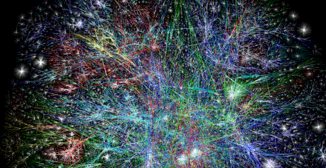
Figure 1-1. Barrett Lyon, “Mapping the Internet,” 2003
Table 1-1 briefly outlines the history of networking before we dive into a few of the important details.
| Year | Event |
|---|---|
1969 |
ARPANET’s first connection test |
1969 |
Telnet 1969 Request for Comments (RFC) 15 drafted |
1971 |
FTP RFC 114 drafted |
1973 |
FTP RFC 354 drafted |
1974 |
TCP RFC 675 by Vint Cerf, Yogen Dalal, and Carl Sunshine drafted |
1980 |
Development of Open Systems Interconnection model begins |
1981 |
IP RFC 760 drafted |
1982 |
NORSAR and University College London left the ARPANET and began using TCP/IP over SATNET |
1984 |
ISO 7498 Open Systems Interconnection (OSI) model published |
1991 |
National Information Infrastructure (NII) Bill passed with Al Gore’s help |
1991 |
First version of Linux released |
2015 |
First version of Kubernetes released |
In its earliest forms, networking was government run or sponsored; in the United States, the Department of Defense (DOD) sponsored the Advanced Research Projects Agency Network (ARPANET), well before Al Gore’s time in politics, which will be relevant in a moment. In 1969, ARPANET was deployed at the University of California–Los Angeles, the Augmentation Research Center at Stanford Research Institute, the University of California–Santa Barbara, and the University of Utah School of Computing. Communication between these nodes was not completed until 1970, when they began using the Network Control Protocol (NCP). NCP led to the development and use of the first computer-to-computer protocols like Telnet and File Transfer Protocol (FTP).
The success of ARPANET and NCP, the first protocol to power ARPANET, led to NCP’s downfall. It could not keep up with the demands of the network and the variety of networks connected. In 1974, Vint Cerf, Yogen Dalal, and Carl Sunshine began drafting RFC 675 for Transmission Control Protocol (TCP). (You’ll learn more about RFCs in a few paragraphs.) TCP would go on to become the standard for network connectivity. TCP allowed for exchanging packets across different types of networks. In 1981, the Internet Protocol (IP), defined in RFC 791, helped break out the responsibilities of TCP into a separate protocol, increasing the modularity of the network. In the following years, many organizations, including the DOD, adopted TCP as the standard. By January 1983, TCP/IP had become the only approved protocol on ARPANET, replacing the earlier NCP because of its versatility and modularity.
A competing standards organization, the International Organization for Standardization (ISO), developed and published ISO 7498, “Open Systems Interconnection Reference Model,” which detailed the OSI model. With its publication also came the protocols to support it. Unfortunately, the OSI model protocols never gained traction and lost out to the popularity of TCP/IP. The OSI model is still an excellent learning tool for understanding the layered approach to networking, however.
In 1991, Al Gore invented the internet (well, really he helped pass the National Information Infrastructure [NII] Bill), which helped lead to the creation of the Internet Engineering Task Force (IETF). Nowadays standards for the internet are under the management of the IETF, an open consortium of leading experts and companies in the field of networking, like Cisco and Juniper. RFCs are published by the Internet Society and the Internet Engineering Task Force. RFCs are prominently authored by individuals or groups of engineers and computer scientists, and they detail their processes, operations, and applications for the internet’s functioning.
An IETF RFC has two states:
- Proposed Standard
-
A protocol specification has reached enough community support to be considered a standard. The designs are stable and well understood. A proposed standard can be deployed, implemented, and tested. It may be withdrawn from further consideration, however.
- Internet Standard
-
Per RFC 2026: “In general, an internet standard is a stable specification and well understood, technically competent, has multiple, independent, and interoperable implementations with substantial operational experience, enjoys significant public support, and is recognizably useful in some parts of the internet.”
Note
Draft standard is a third classification that was discontinued in 2011.
There are thousands of internet standards defining how to implement protocols for all facets of networking, including wireless, encryption, and data formats, among others. Each one is implemented by contributors of open source projects and privately by large organizations like Cisco.
A lot has happened in the nearly 50 years since those first connectivity tests. Networks have grown in complexity and abstractions, so let’s start with the OSI model.
OSI Model
The OSI model is a conceptual framework for describing how two systems communicate over a network. The OSI model breaks down the responsibility of sending data across networks into layers. This works well for educational purposes to describe the relationships between each layer’s responsibility and how data gets sent over networks. Interestingly enough, it was meant to be a protocol suite to power networks but lost to TCP/IP.
Here are the ISO standards that outline the OSI model and protocols:
-
ISO/IEC 7498-1, “The Basic Model”
-
ISO/IEC 7498-2, “Security Architecture”
-
ISO/IEC 7498-3, “Naming and Addressing”
-
ISO/IEC 7498-4, “Management Framework”
The ISO/IEC 7498-1 describes what the OSI model attempts to convey:
5.2.2.1 The basic structuring technique in the Reference Model of Open Systems Interconnection is layering. According to this technique, each open system is viewed as logically composed of an ordered set of (N)-subsystems…Adjacent (N)-subsystems communicate through their common boundary. (N)-subsystems of the same rank (N) collectively form the (N)-layer of the Reference Model of Open Systems Interconnection. There is one and only one (N)-subsystem in an open system for layer N. An (N)-subsystem consists of one or several (N)-entities. Entities exist in each (N)-layer. Entities in the same (N)-layer are termed peer-(N)-entities. Note that the highest layer does not have an (N+l)-layer above it, and the lowest layer does not have an (N-1)-layer below it.
The OSI model description is a complex and exact way of saying networks have layers like cakes or onions. The OSI model breaks the responsibilities of the network into seven distinct layers, each with different functions to aid in transmitting information from one system to another, as shown in Figure 1-2. The layers encapsulate information from the layer below it; these layers are Application, Presentation, Session, Transport, Network, Data Link, and Physical. Over the next few pages, we will go over each layer’s functionality and how it sends data between two systems.

Figure 1-2. OSI model layers
Each layer takes data from the previous layer and encapsulates it to make its Protocol Data Unit (PDU). The PDU is used to describe the data at each layer. PDUs are also part of TCP/IP. The applications of the Session layer are considered “data” for the PDU, preparing the application information for communication. Transport uses ports to distinguish what process on the local system is responsible for the data. The Network layer PDU is the packet. Packets are distinct pieces of data routed between networks. The Data Link layer is the frame or segment. Each packet is broken up into frames, checked for errors, and sent out on the local network. The Physical layer transmits the frame in bits over the medium. Next we will outline each layer in detail:
- Application
-
The Application layer is the top layer of the OSI model and is the one the end user interacts with every day. This layer is not where actual applications live, but it provides the interface for applications that use it like a web browser or Office 365. The single biggest interface is HTTP; you are probably reading this book on a web page hosted by an O’Reilly web server. Other examples of the Application layer that we use daily are DNS, SSH, and SMTP. Those applications are responsible for displaying and arranging data requested and sent over the network.
- Presentation
-
This layer provides independence from data representation by translating between application and network formats. It can be referred to as the syntax layer. This layer allows two systems to use different encodings for data and still pass data between them. Encryption is also done at this layer, but that is a more complicated story we’ll save for “TLS”.
- Session
-
The Session layer is responsible for the duplex of the connection, in other words, whether sending and receiving data at the same time. It also establishes procedures for performing checkpointing, suspending, restarting, and terminating a session. It builds, manages, and terminates the connections between the local and remote applications.
- Transport
-
The Transport layer transfers data between applications, providing reliable data transfer services to the upper layers. The Transport layer controls a given connection’s reliability through flow control, segmentation and desegmentation, and error control. Some protocols are state- and connection-oriented. This layer tracks the segments and retransmits those that fail. It also provides the acknowledgment of successful data transmission and sends the next data if no errors occurred. TCP/IP has two protocols at this layer: TCP and User Datagram Protocol (UDP).
- Network
-
The Network layer implements a means of transferring variable-length data flows from a host on one network to a host on another network while sustaining service quality. The Network layer performs routing functions and might also perform fragmentation and reassembly while reporting delivery errors. Routers operate at this layer, sending data throughout the neighboring networks. Several management protocols belong to the Network layer, including routing protocols, multicast group management, network-layer information, error handling, and network-layer address assignment, which we will discuss further in “TCP/IP”.
- Data Link
-
This layer is responsible for the host-to-host transfers on the same network. It defines the protocols to create and terminate the connections between two devices. The Data Link layer transfers data between network hosts and provides the means to detect and possibly correct errors from the Physical layer. Data Link frames, the PDU for layer 2, do not cross the boundaries of a local network.
- Physical
-
The Physical layer is represented visually by an Ethernet cord plugged into a switch. This layer converts data in the form of digital bits into electrical, radio, or optical signals. Think of this layer as the physical devices, like cables, switches, and wireless access points. The wire signaling protocols are also defined at this layer.
Note
There are many mnemonics to remember the layers of the OSI model; our favorite is All People Seem To Need Data Processing.
Table 1-2 summarizes the OSI layers.
| Layer number | Layer name | Protocol data unit | Function overview |
|---|---|---|---|
7 |
Application |
Data |
High-level APIs and application protocols like HTTP, DNS, and SSH. |
6 |
Presentation |
Data |
Character encoding, data compression, and encryption/decryption. |
5 |
Session |
Data |
Continuous data exchanges between nodes are managed here: how much data to send, when to send more. |
4 |
Transport |
Segment, datagram |
Transmission of data segments between endpoints on a network, including segmentation, acknowledgment, and multiplexing. |
3 |
Network |
Packet |
Structuring and managing addressing, routing, and traffic control for all endpoints on the network. |
2 |
Data Link |
Frame |
Transmission of data frames between two nodes connected by a Physical layer. |
1 |
Physical |
Bit |
Sending and receiving of bitstreams over the medium. |
The OSI model breaks down all the necessary functions to send a data packet over a network between two hosts. In the late 1980s and early 1990s, it lost out to TCP/IP as the standard adopted by the DOD and all other major players in networking. The standard defined in ISO 7498 gives a brief glimpse into the implementation details that were considered by most at the time to be complicated, inefficient, and to an extent unimplementable. The OSI model at a high level still allows those learning networking to comprehend the basic concepts and challenges in networking. In addition, these terms and functions are used in the TCP/IP model covered in the next section and ultimately in Kubernetes abstractions. Kubernetes services break out each function depending on the layer it is operating at, for example, a layer 3 IP address or a layer 4 port; you will learn more about that in Chapter 4. Next, we will do a deep dive into the TCP/IP suite with an example walk-through.
TCP/IP
TCP/IP creates a heterogeneous network with open protocols that are independent of the operating system and architectural differences. Whether the hosts are running Windows, Linux, or another OS, TCP/IP allows them to communicate; TCP/IP does not care if you are running Apache or Nginx for your web server at the Application layer. The separation of responsibilities similar to the OSI model makes that possible. In Figure 1-3, we compare the OSI model to TCP/IP.
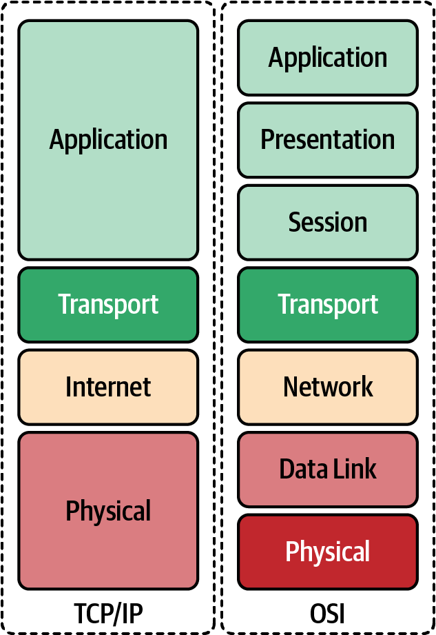
Figure 1-3. OSI model compared to TCP/IP
Here we expand on the differences between the OSI model and the TCP/IP:
- Application
-
In TCP/IP, the Application layer comprises the communications protocols used in process-to-process communications across an IP network. The Application layer standardizes communication and depends upon the underlying Transport layer protocols to establish the host-to-host data transfer. The lower Transport layer also manages the data exchange in network communications. Applications at this layer are defined in RFCs; in this book, we will continue to use HTTP, RFC 7231 as our example for the Application layer.
- Transport
-
TCP and UDP are the primary protocols of the Transport layer that provide host-to-host communication services for applications. Transport protocols are responsible for connection-oriented communication, reliability, flow control, and multiplexing. In TCP, the window size manages flow control, while UDP does not manage the congestion flow and is considered unreliable; you’ll learn more about that in “UDP”. Each port identifies the host process responsible for processing the information from the network communication. HTTP uses the well-known port 80 for nonsecure communication and 443 for secure communication. Each port on the server identifies its traffic, and the sender generates a random port locally to identify itself. The governing body that manages port number assignments is the Internet Assigned Number Authority (IANA); there are 65,535 ports.
- Internet
-
The Internet, or Network layer, is responsible for transmitting data between networks. For an outgoing packet, it selects the next-hop host and transmits it to that host by passing it to the appropriate link-layer. Once the packet is received by the destination, the Internet layer will pass the packet payload up to the appropriate Transport layer protocol.
IP provides the fragmentation or defragmentation of packets based on the maximum transmission unit (MTU); this is the maximum size of the IP packet. IP makes no guarantees about packets’ proper arrival. Since packet delivery across diverse networks is inherently unreliable and failure-prone, that burden is with the endpoints of a communication path, rather than on the network. The function of providing service reliability is in the Transport layer. A checksum ensures that the information in a received packet is accurate, but this layer does not validate data integrity. The IP address identifies packets on the network.
- Link
-
The Link layer in the TCP/IP model comprises networking protocols that operate only on the local network that a host connects to. Packets are not routed to nonlocal networks; that is the Internet layer’s role. Ethernet is the dominant protocol at this layer, and hosts are identified by the link-layer address or commonly their Media Access Control addresses on their network interface cards. Once determined by the host using Address Resolution Protocol 9 (ARP), data sent off the local network is processed by the Internet layer. This layer also includes protocols for moving packets between two Internet layer hosts.
- Physical layer
-
The Physical layer defines the components of the hardware to use for the network. For example, the Physical network layer stipulates the physical characteristics of the communications media. The Physical layer of TCP/IP details hardware standards such as IEEE 802.3, the specification for Ethernet network media. Several interpretations of RFC 1122 for the Physical layer are included with the other layers; we have added this for completeness.
Throughout this book, we will use the minimal Golang web server (also called Go) from Example 1-1 to show various levels of networking components from tcpdump, a Linux syscall, to show how Kubernetes abstracts the syscalls. This section will use it to demonstrate what is happening at the Application, Transport, Network, and Data Link layers.
Application
As mentioned, Application is the highest layer in the TCP/IP stack; it is where the user interacts with data before it gets sent over the network. In our example walk-through, we are going to use Hypertext Transfer Protocol (HTTP) and a simple HTTP transaction to demonstrate what happens at each layer in the TCP/IP stack.
HTTP
HTTP is responsible for sending and receiving Hypertext Markup Language (HTML) documents—you know, a web page. A vast majority of what we see and do on the internet is over HTTP: Amazon purchases, Reddit posts, and tweets all use HTTP. A client will make an HTTP request to our minimal Golang web server from Example 1-1, and it will send an HTTP response with “Hello” text. The web server runs locally in an Ubuntu virtual machine to test the full TCP/IP stack.
Note
See the example code repository for full instructions.
Example 1-1. Minimal web server in Go
packagemainimport("fmt""net/http")funchello(whttp.ResponseWriter,_*http.Request){fmt.Fprintf(w,"Hello")}funcmain(){http.HandleFunc("/",hello)http.ListenAndServe("0.0.0.0:8080",nil)}
In our Ubuntu virtual machine we need to start our minimal web server, or if you have Golang installed locally, you can just run this:
go run web-server.go
Let’s break down the request for each layer of the TPC/IP stack.
cURL is the requesting client for our HTTP request example. Generally, for a web page, the client would be a web browser, but we’re using cURL to simplify and show the command line.
Note
cURL is meant for uploading and downloading data specified with a URL. It is a client-side program (the c) to request data from a URL and return the response.
In Example 1-2, we can see each part of the HTTP request that the cURL client is making and the response. Let’s review what all those options and outputs are.
Example 1-2. Client request
○→curllocalhost:8080-vvv*Trying::1...*TCP_NODELAYset*Connectedtolocalhost(::1)port8080>GET/HTTP/1.1>Host:localhost:8080>User-Agent:curl/7.64.1>Accept:*/*><HTTP/1.1200OK<Date:Sat,25Jul202014:57:46GMT<Content-Length:5<Content-Type:text/plain;charset=utf-8<*Connection#0 to host localhost left intactHello*Closingconnection0

curllocalhost:8080-vvv: This is thecurlcommand that opens a connection to the locally running web server,localhoston TCP port 8080.-vvvsets the verbosity of the output so we can see everything happening with the request. Also,TCP_NODELAYinstructs the TCP connection to send the data without delay, one of many options available to the client to set.
Connectedtolocalhost(::1)port8080: It worked! cURL connected to the web server on localhost and over port 8080.
Get/HTTP/1.1: HTTP has several methods for retrieving or updating information. In our request, we are performing an HTTP GET to retrieve our “Hello” response. The forward slash is the next part, a Uniform Resource Locator (URL), which indicates where we are sending the client request to the server. The last section of this header is the version of HTTP the server is using, 1.1.
Host:localhost:8080: HTTP has several options for sending information about the request. In our request, the cURL process has set the HTTP Host header. The client and server can transmit information with an HTTP request or response. An HTTP header contains its name followed by a colon (:) and then its value.
User-Agent: cURL/7.64.1: The user agent is a string that indicates the computer program making the HTTP request on behalf of the end user; it is cURL in our context. This string often identifies the browser, its version number, and its host operating system.
Accept:*/*: This header instructs the web server what content types the client understands. Table 1-3 shows examples of common content types that can be sent.
HTTP/1.1200OK: This is the server response to our request. The server responds with the HTTP version and the response status code. There are several possible responses from the server. A status code of 200 indicates the response was successful. 1XX means informational, 2XX means successful, 3XX means redirects, 4XX responses indicate there are issues with the requests, and 5XX generally refers to issues from the server.
Date: Sat, July 25, 2020, 14:57:46 GMT: TheDateheader field represents the date and time at which the message originated. The sender generates the value as the approximate date and time of message generation.
Content-Length: 5: TheContent-Lengthheader indicates the size of the message body, in bytes, sent to the recipient; in our case, the message is 5 bytes.
Content-Type: text/plain; charset=utf-8: TheContent-Typeentity header is used to indicate the resource’s media type. Our response is indicating that it is returning a plain-text file that is UTF-8 encoded.
Hello* Closing connection 0: This prints out the response from our web server and closes out the HTTP connection.
| Type | Description |
|---|---|
application |
Any kind of binary data that doesn’t fall explicitly into one of the other types. Common examples include application/json, application/pdf, application/pkcs8, and application/zip. |
audio |
Audio or music data. Examples include audio/mpeg and audio/vorbis. |
font |
Font/typeface data. Common examples include font/woff, font/ttf, and font/otf. |
image |
Image or graphical data including both bitmap and vector such as animated GIF or APNG. Common examples are image/jpg, image/png, and image/svg+xml. |
model |
Model data for a 3D object or scene. Examples include model/3mf and model/vrml. |
text |
Text-only data including human-readable content, source code, or text data. Examples include text/plain, text/csv, and text/html. |
video |
Video data or files, such as video/mp4. |
This is a simplistic view that happens with every HTTP request. Today, a single web page makes an exorbitant number of requests with one load of a page, and in just a matter of seconds! This is a brief example for cluster administrators of how HTTP (and for that matter, the other seven layers’ applications) operate. We will continue to build our knowledge of how this request is completed at each layer of the TCP/IP stack and then how Kubernetes completes those same requests. All this data is formatted and options are set at layer 7, but the real heavy lifting is done at the lower layers of the TCP/IP stack, which we will go over in the next sections.
Transport
The Transport layer protocols are responsible for connection-oriented communication, reliability, flow control, and multiplexing; this is mostly true of TCP. We’ll describe the differences in the following sections. Our Golang web server is a layer 7 application using HTTP; the Transport layer that HTTP relies on is TCP.
TCP
As already mentioned, TCP is a connection-oriented, reliable protocol, and it provides flow control and multiplexing. TCP is considered connection-oriented because it manages the connection state through the life cycle of the connection. In TCP, the window size manages flow control, unlike UDP, which does not manage the congestion flow. In addition, UDP is unreliable, and data may arrive out of sequence. Each port identifies the host process responsible for processing the information from the network communication. TCP is known as a host-to-host layer protocol. To identify the process on the host responsible for the connection, TCP identifies the segments with a 16-bit port number. HTTP servers use the well-known port of 80 for nonsecure communication and 443 for secure communication using Transport Layer Security (TLS). Clients requesting a new connection create a source port local in the range of 0–65534.
To understand how TCP performs multiplexing, let’s review a simple HTML page retrieval:
-
In a web browser, type in a web page address.
-
The browser opens a connection to transfer the page.
-
The browser opens connections for each image on the page.
-
The browser opens another connection for the external CSS.
-
Each of these connections uses a different set of virtual ports.
-
All the page’s assets download simultaneously.
-
The browser reconstructs the page.
Let’s walk through how TCP manages multiplexing with the information provided in the TCP segment headers:
Source port(16 bits)-
This identifies the sending port.
Destination port(16 bits)Sequence number(32 bits)-
If the SYN flag is set, this is the initial sequence number. The sequence number of the first data byte and the acknowledged number in the corresponding ACK is this sequence number plus 1. It is also used to reassemble data if it arrives out of order.
Acknowledgment number(32 bits)-
If the ACK flag is set, then this field’s value is the next sequence number of the ACK the sender is expecting. This acknowledges receipt of all preceding bytes (if any). Each end’s first ACK acknowledges the other end’s initial sequence number itself, but no data has been sent.
Data offset(4 bits)Reserved(3 bits)Flags(9 bits)-
There are nine 1-bit fields defined for the TCP header:
-
NS–ECN-nonce: Concealment protection.
-
CWR: Congestion Window Reduced; the sender reduced its sending rate.
-
ECE: ECN Echo; the sender received an earlier congestion notification.
-
URG: Urgent; the Urgent Pointer field is valid, but this is rarely used.
-
ACK: Acknowledgment; the Acknowledgment Number field is valid and is always on after a connection is established.
-
PSH: Push; the receiver should pass this data to the application as soon as possible.
-
RST: Reset the connection or connection abort, usually because of an error.
-
SYN: Synchronize sequence numbers to initiate a connection.
-
FIN: The sender of the segment is finished sending data to its peer.
-
Window size(16 bits)Checksum(16 bits)-
The checksum field is used for error checking of the TCP header.
Urgent pointer(16 bits)-
This is an offset from the sequence number indicating the last urgent data byte.
OptionsPadding-
The TCP header padding is used to ensure that the TCP header ends, and data begins on a 32-bit boundary.
Data-
This is the piece of application data being sent in this segment.
In Figure 1-4, we can see all the TCP segment headers that provide metadata about the TCP streams.
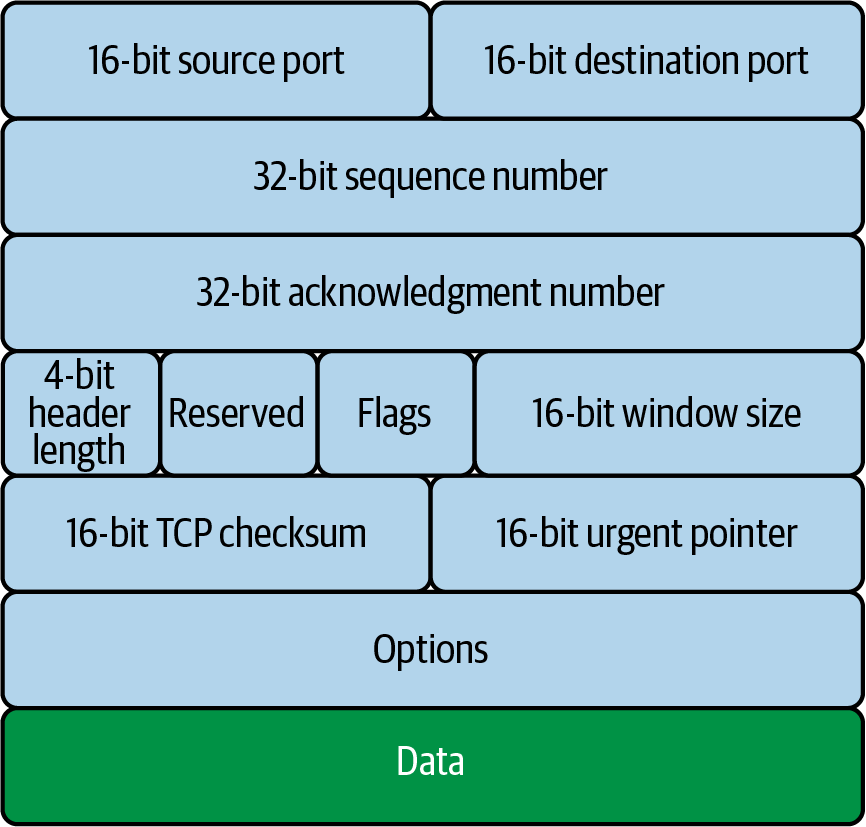
Figure 1-4. TCP segment header
These fields help manage the flow of data between two systems. Figure 1-5 shows how each step of the TCP/IP stack sends data from one application on one host, through a network communicating at layers 1 and 2, to get data to the destination host.
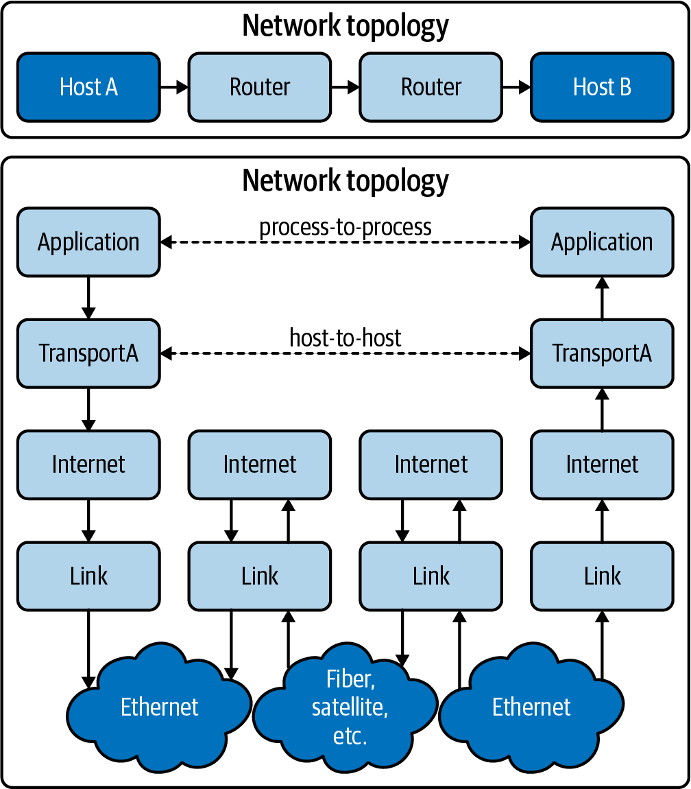
Figure 1-5. tcp/ip data flow
In the next section, we will show how TCP uses these fields to initiate a connection through the three-way handshake.
TCP handshake
TCP uses a three-way handshake, pictured in Figure 1-6, to create a connection by exchanging information along the way with various options and flags:
-
The requesting node sends a connection request via a SYN packet to get the transmission started.
-
If the receiving node is listening on the port the sender requests, the receiving node replies with a SYN-ACK, acknowledging that it has heard the requesting node.
-
The requesting node returns an ACK packet, exchanging information and letting them know the nodes are good to send each other information.
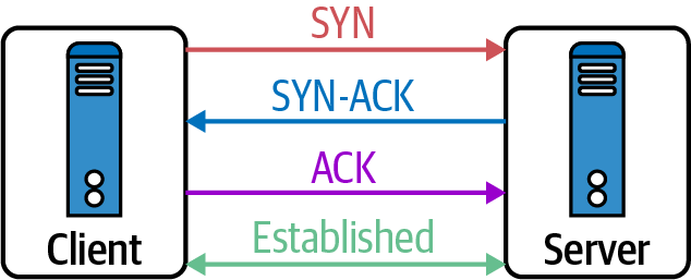
Figure 1-6. TCP three-way handshake
Now the connection is established. Data can be transmitted over the physical medium, routed between networks, to find its way to the local destination—but how does the endpoint know how to handle the information? On the local and remote hosts, a socket gets created to track this connection. A socket is just a logical endpoint for communication. In Chapter 2, we will discuss how a Linux client and server handle sockets.
TCP is a stateful protocol, tracking the connection’s state throughout its life cycle. The state of the connection depends on both the sender and the receiver agreeing where they are in the connection flow. The connection state is concerned about who is sending and receiving data in the TCP stream. TCP has a complex state transition for explaining when and where the connection is, using the 9-bit TCP flags in the TCP segment header, as you can see in Figure 1-7.
The TCP connection states are:
LISTEN(server)-
Represents waiting for a connection request from any remote TCP and port
SYN-SENT(client)-
Represents waiting for a matching connection request after sending a connection request
SYN-RECEIVED(server)-
Represents waiting for a confirming connection request acknowledgment after having both received and sent a connection request
ESTABLISHED(both server and client)-
Represents an open connection; data received can be delivered to the user—the intermediate state for the data transfer phase of the connection
FIN-WAIT-1(both server and client)-
Represents waiting for a connection termination request from the remote host
FIN-WAIT-2(both server and client)-
Represents waiting for a connection termination request from the remote TCP
CLOSE-WAIT(both server and client)-
Represents waiting for a local user’s connection termination request
CLOSING(both server and client)-
Represents waiting for a connection termination request acknowledgment from the remote TCP
LAST-ACK(both server and client)-
Represents waiting for an acknowledgment of the connection termination request previously sent to the remote host
TIME-WAIT(either server or client)-
Represents waiting for enough time to pass to ensure the remote host received the acknowledgment of its connection termination request
CLOSED(both server and client)

Figure 1-7. TCP state transition diagram
Example 1-3 is a sample of a Mac’s TCP connections, their state, and the addresses for both ends of the connection.
Example 1-3. TCP connection states
○ → netstat -ap TCP Active internet connections(including servers)Proto Recv-Q Send-Q Local Address Foreign Address(state)tcp6002607:fcc8:a205:c.53606 g2600-1407-2800-.https ESTABLISHED tcp6002607:fcc8:a205:c.53603 g2600-1408-5c00-.https ESTABLISHED tcp400192.168.0.17.53602 ec2-3-22-64-157..https ESTABLISHED tcp6002607:fcc8:a205:c.53600 g2600-1408-5c00-.https ESTABLISHED tcp400192.168.0.17.53598 164.196.102.34.b.https ESTABLISHED tcp400192.168.0.17.53597 server-99-84-217.https ESTABLISHED tcp400192.168.0.17.53596 151.101.194.137.https ESTABLISHED tcp400192.168.0.17.53587 ec2-52-27-83-248.https ESTABLISHED tcp6002607:fcc8:a205:c.53586 iad23s61-in-x04..https ESTABLISHED tcp6002607:fcc8:a205:c.53542 iad23s61-in-x04..https ESTABLISHED tcp400192.168.0.17.53536 ec2-52-10-162-14.https ESTABLISHED tcp400192.168.0.17.53530 server-99-84-178.https ESTABLISHED tcp400192.168.0.17.53525 ec2-52-70-63-25..https ESTABLISHED tcp6002607:fcc8:a205:c.53480 upload-lb.eqiad..https ESTABLISHED tcp6002607:fcc8:a205:c.53477 text-lb.eqiad.wi.https ESTABLISHED tcp400192.168.0.17.53466 151.101.1.132.https ESTABLISHED tcp400192.168.0.17.53420 ec2-52-0-84-183..https ESTABLISHED tcp400192.168.0.17.53410 192.168.0.18.8060 CLOSE_WAIT tcp6002607:fcc8:a205:c.53408 2600:1901:1:c36:.https ESTABLISHED tcp400192.168.0.17.53067 ec2-52-40-198-7..https ESTABLISHED tcp400192.168.0.17.53066 ec2-52-40-198-7..https ESTABLISHED tcp400192.168.0.17.53055 ec2-54-186-46-24.https ESTABLISHED tcp400localhost.16587 localhost.53029 ESTABLISHED tcp400localhost.53029 localhost.16587 ESTABLISHED tcp4600*.16587 *.* LISTEN tcp65602607:fcc8:a205:c.56210 ord38s08-in-x0a..https CLOSE_WAIT tcp6002607:fcc8:a205:c.51699 2606:4700::6810:.https ESTABLISHED tcp400192.168.0.17.64407do-77.lastpass.c.https ESTABLISHED tcp400192.168.0.17.64396 ec2-54-70-97-159.https ESTABLISHED tcp400192.168.0.17.60612 ac88393aca5853df.https ESTABLISHED tcp400192.168.0.17.58193 47.224.186.35.bc.https ESTABLISHED tcp400localhost.63342 *.* LISTEN tcp400localhost.6942 *.* LISTEN tcp400192.168.0.17.55273 ec2-50-16-251-20.https ESTABLISHED
Now that we know more about how TCP constructs and tracks connections, let’s review the HTTP request for our
web server at the Transport layer using TCP. To accomplish this, we use a command-line tool called tcpdump.
tcpdump
tcpdumpprints out a description of the contents of packets on a network interface that matches the boolean expression.tcpdump man page
tcpdump allows administrators and users to display all the packets processed on the system and filter them out
based on many TCP segment header details. In the request, we filter all packets with the destination port
8080 on the network interface labeled lo0; this is the local loopback interface on the Mac. Our web server is
running on 0.0.0.0:8080. Figure 1-8 shows where tcpdump is collecting data in reference to the full TCP/IP stack,
between the network interface card (NIC) driver and layer 2.
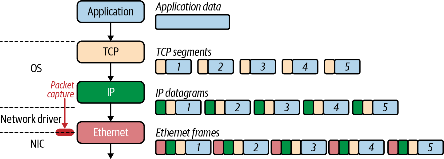
Figure 1-8. tcpdump packet capture
Note
A loopback interface is a logical, virtual interface on a device. A loopback interface is not a physical interface like Ethernet interface. Loopback interfaces are always up and running and always available, even if other interfaces are down on the host.
The general format of a tcpdump output will contain the following fields: tos,TTL, id, offset, flags, proto, length, and options. Let’s review these:
tosTTLidoffset-
The fragment offset field; it is printed whether this is part of a fragmented datagram or not.
flags-
The DF, Don’t Fragment, flag, which indicates that the packet cannot be fragmented for transmission. When unset, it indicates that the packet can be fragmented. The MF, More Fragments, flag indicates there are packets that contain more fragments and when unset, it indicates that no more fragments remain.
protolengthoptions
Systems that support checksum offloading and IP, TCP, and UDP checksums are calculated on the NIC before being
transmitted on the wire. Since we are running a tcpdump packet capture before the NIC, errors like cksum
0xfe34 (incorrect -> 0xb4c1) appear in the output of Example 1-4.
To produce the output for Example 1-4, open another terminal and start a tcpdump trace on the loopback for only TCP
and port 8080; otherwise, you will see a lot of other packets not relevant to our example. You’ll need to use
escalated privileges to trace packets, so that means using sudo in this case.
Example 1-4. tcpdump
○→sudotcpdump-ilo0tcpport8080-vvvtcpdump:listeningonlo0,link-typeNULL(BSDloopback),capturesize262144bytes08:13:55.009899localhost.50399>localhost.http-alt:Flags[S],cksum0x0034(incorrect->0x1bd9),seq2784345138,win65535,options[mss16324,nop,wscale6,nop,nop,TSval587364215ecr0,sackOK,eol],length008:13:55.009997localhost.http-alt>localhost.50399:Flags[S.],cksum0x0034(incorrect->0xbe5a),seq195606347,ack2784345139,win65535,options[mss16324,nop,wscale6,nop,nop,TSval587364215ecr587364215,sackOK,eol],length008:13:55.010012localhost.50399>localhost.http-alt:Flags[.],cksum0x0028(incorrect->0x1f58),seq1,ack1,win6371,options[nop,nop,TSval587364215ecr587364215],length0v08:13:55.010021localhost.http-alt>localhost.50399:Flags[.],cksum0x0028(incorrect->0x1f58),seq1,ack1,win6371,options[nop,nop,TSval587364215ecr587364215],length008:13:55.010079localhost.50399>localhost.http-alt:Flags[P.],cksum0x0076(incorrect->0x78b2),seq1:79,ack1,win6371,options[nop,nop,TSval587364215ecr587364215],length78:HTTP,length:78GET/HTTP/1.1Host:localhost:8080User-Agent:curl/7.64.1Accept:*/*08:13:55.010102localhost.http-alt>localhost.50399:Flags[.],cksum0x0028(incorrect->0x1f0b),seq1,ack79,win6370,options[nop,nop,TSval587364215ecr587364215],length008:13:55.010198localhost.http-alt>localhost.50399:Flags[P.],cksum0x00a1(incorrect->0x05d7),seq1:122,ack79,win6370,options[nop,nop,TSval587364215ecr587364215],length121:HTTP,length:121HTTP/1.1200OKDate:Wed,19Aug202012:13:55GMTContent-Length:5Content-Type:text/plain;charset=utf-8Hello[!http]08:13:55.010219localhost.50399>localhost.http-alt:Flags[.],cksum0x0028(incorrect->0x1e93),seq79,ack122,win6369,options[nop,nop,TSval587364215ecr587364215],length008:13:55.010324localhost.50399>localhost.http-alt:Flags[F.],cksum0x0028(incorrect->0x1e92),seq79,ack122,win6369,options[nop,nop,TSval587364215ecr587364215],length008:13:55.010343localhost.http-alt>localhost.50399:Flags[.],cksum0x0028(incorrect->0x1e91),seq122,\ack80,win6370,options[nop,nop,TSval587364215ecr587364215],length008:13:55.010379localhost.http-alt>localhost.50399:Flags[F.],cksum0x0028(incorrect->0x1e90),seq122,ack80,win6370,options[nop,nop,TSval587364215ecr587364215],length008:13:55.010403localhost.50399>localhost.http-alt:Flags[.],cksum0x0028(incorrect->0x1e91),seq80,ack123,win6369,options[nop,nop,TSval587364215ecr587364215],length012packetscaptured,12062packetsreceivedbyfilter0packetsdroppedbykernel.

This is the start of the
tcpdumpcollection with its command and all of its options. Thesudopacket captures the required escalated privileges.tcpdumpis thetcpdumpbinary.-i lo0is the interface from which we want to capture packets.dst port 8080is the matching expression that the man page discussed; here we are matching on all packets destined for TCP port 8080, which is the port the web service is listening to for requests.-vis the verbose option, which allows us to see more details from thetcpdumpcapture.
Feedback from
tcpdumpletting us know about thetcpdumpfilter running.
This is the first packet in the TCP handshake. We can tell it’s the SYN because the flags bit is set with
[S], and the sequence number is set to2784345138by cURL, with the localhost process number being50399.
The SYN-ACK packet is the the one filtered by
tcpdumpfrom thelocalhost.http-altprocess, the Golang web server. The flag is to[S.], so it is a SYN-ACK. The packet sends195606347as the next sequence number, and ACK2784345139is set to acknowledge the previous packet.
The acknowledgment packet from cURL is now sent back to the server with the ACK flag set,
[.], with the ACK and SYN numbers set to 1, indicating it is ready to send data.
The acknowledgment number is set to 1 to indicate the client’s SYN flag’s receipt in the opening data push.

The TCP connection is established; both the client and server are ready for data transmission. The next packets are our data transmissions of the HTTP request with the flag set to a data push and ACK,
[P.]. The previous packets had a length of zero, but the HTTP request is 78 bytes long, with a sequence number of 1:79.
The server acknowledges the receipt of the data transmission, with the ACK flag set,
[.], by sending the acknowledgment number of 79.
This packet is the HTTP server’s response to the cURL request. The data push flag is set,
[P.], and it acknowledges the previous packet with an ACK number of 79. A new sequence number is set with the data transmission, 122, and the data length is 121 bytes.
The cURL client acknowledges the receipt of the packet with the ACK flag set, sets the acknowledgment number to 122, and sets the sequence number to 79.

The start of closing the TCP connection, with the client sending the FIN-ACK packet, the
[F.], acknowledging the receipt of the previous packet, number 122, and a new sequence number to 80.
The server increments the acknowledgment number to 80 and sets the ACK flag.

TCP requires that both the sender and the receiver set the FIN packet for closing the connection. This is the packet where the FIN and ACK flags are set.

This is the final ACK from the client, with acknowledgment number 123. The connection is closed now.

tcpdumpon exit lets us know the number of packets in this capture, the total number of the packets captured during thetcpdump, and how many packets were dropped by the operating system.
tcpdump is an excellent troubleshooting application for network engineers as well as cluster administrators.
Being able to verify connectivity at many levels in the cluster and the network are valuable skills to have. You will
see in Chapter 6 how useful tcpdump can be.
Our example was a simple HTTP application using TCP. All of this data was sent over the network in plain text. While this example was a simple Hello World, other requests like our bank logins need to have some security. The Transport layer does not offer any security protection for data transiting the network. TLS adds additional security on top of TCP. Let’s dive into that in our next section.
TLS
TLS adds encryption to TCP. TLS is an add-on to the TCP/IP suite and is not considered to be part of the base operation for TCP. HTTP transactions can be completed without TLS but are not secure from eavesdroppers on the wire. TLS is a combination of protocols used to ensure traffic is seen between the sender and the intended recipient. TLS, much like TCP, uses a handshake to establish encryption capabilities and exchange keys for encryption. The following steps detail the TLS handshake between the client and the server, which can also be seen in Figure 1-9:
-
ClientHello: This contains the cipher suites supported by the client and a random number.
-
ServerHello: This message contains the cipher it supports and a random number.
-
ServerCertificate: This contains the server’s certificate and its server public key.
-
ServerHelloDone: This is the end of the ServerHello. If the client receives a request for its certificate, it sends a ClientCertificate message.
-
ClientKeyExchange: Based on the server’s random number, our client generates a random premaster secret, encrypts it with the server’s public key certificate, and sends it to the server.
-
Key Generation: The client and server generate a master secret from the premaster secret and exchange random values.
-
ChangeCipherSpec: Now the client and server swap their ChangeCipherSpec to begin using the new keys for encryption.
-
Finished Client: The client sends the finished message to confirm that the key exchange and authentication were successful.
-
Finished Server: Now, the server sends the finished message to the client to end the handshake.
Kubernetes applications and components will manage TLS for developers, so a basic introduction is required; Chapter 5 reviews more about TLS and Kubernetes.
As demonstrated with our web server, cURL, and tcpdump, TCP is a stateful and reliable protocol for sending data between hosts. Its use of flags, combined with the sequence and acknowledgment number dance it performs, delivers thousands of messages over unreliable networks across the globe. That reliability comes at
a cost, however. Of the 12 packets we set, only two were real data transfers. For applications that do not need reliability such as voice, the overhead that comes with UDP offers an alternative. Now that we understand how TCP works as a reliable connection-oriented protocol, let’s review how UDP differs from TCP.
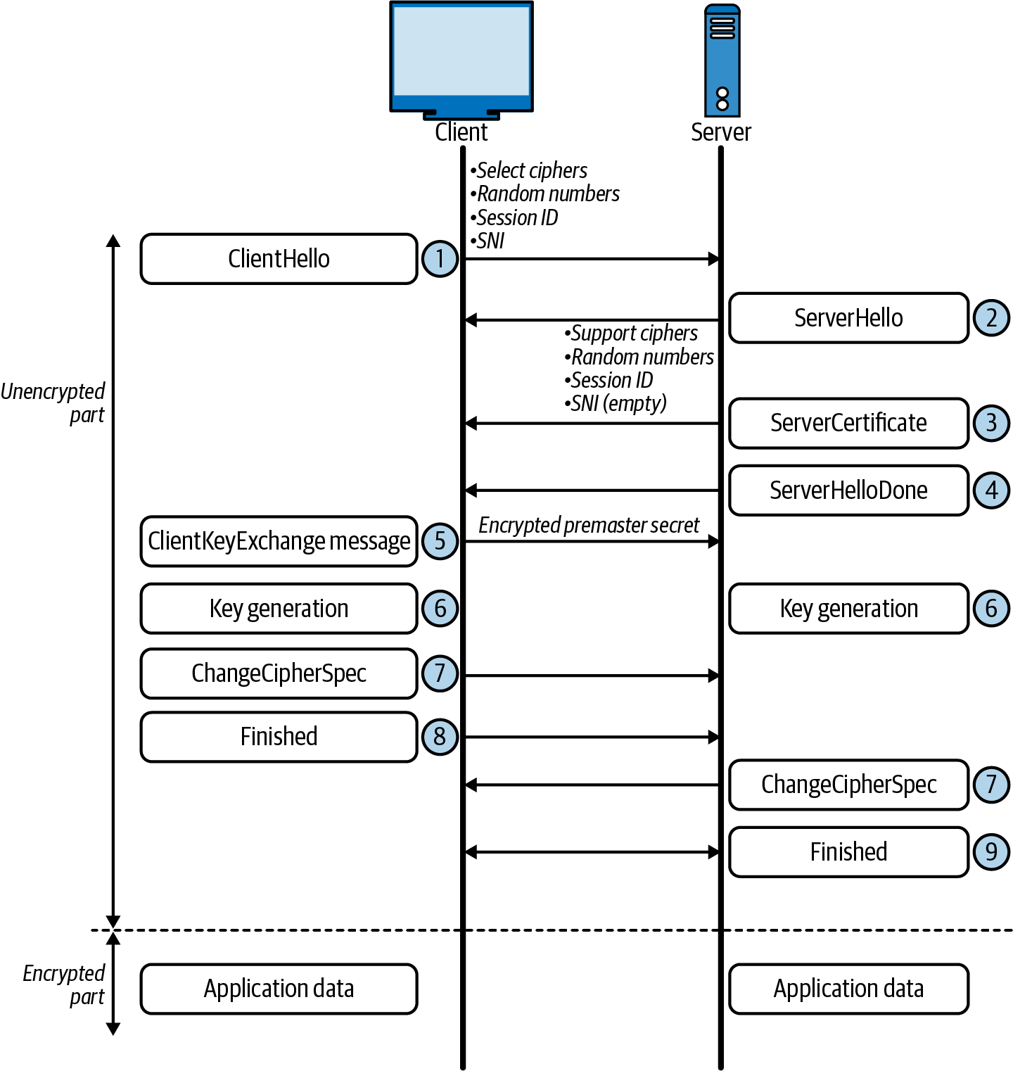
Figure 1-9. TLS handshake
UDP
UDP offers an alternative to applications that do not need the reliability that TCP provides. UDP is an excellent choice for applications that can withstand packet loss such as voice and DNS. UDP offers little overhead from a network perspective, only having four fields and no data acknowledgment, unlike its verbose brother TCP.
It is transaction-oriented, suitable for simple query and response protocols like the Domain Name System (DNS) and Simple Network Management Protocol (SNMP). UDP slices a request into datagrams, making it capable for use with other protocols for tunneling like a virtual private network (VPN). It is lightweight and straightforward, making it great for bootstrapping application data in the case of DHCP. The stateless nature of data transfer makes UDP perfect for applications, such as voice, that can withstand packet loss—did you hear that? UDP’s lack of retransmit also makes it an apt choice for streaming video.
Let’s look at the small number of headers required in a UDP datagram (see Figure 1-10):
Source port number(2 bytes)-
Identifies the sender’s port. The source host is the client; the port number is ephemeral. UDP ports have well-known numbers like DNS on 53 or DHCP 67/68.
Destination port number(2 bytes)Length(2 bytes)-
Specifies the length in bytes of the UDP header and UDP data. The minimum length is 8 bytes, the length of the header.
Checksum(2 bytes)-
Used for error checking of the header and data. It is optional in IPv4, but mandatory in IPv6, and is all zeros if unused.
UDP and TCP are general transport protocols that help ship and receive data between hosts. Kubernetes supports both protocols on the network, and services allow users to load balance many pods using services. Also important to note is that in each service, developers must define the transport protocol; if they do not TCP is the default used.
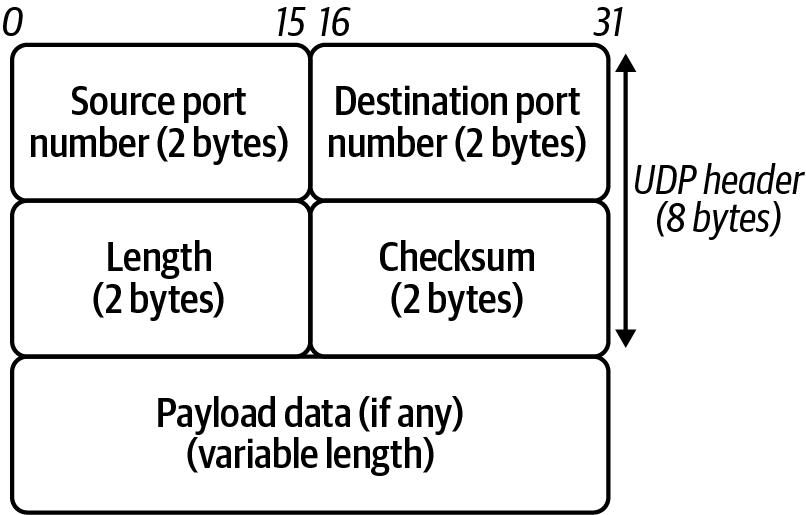
Figure 1-10. UDP header
The next layer in the TCP/IP stack is the Internetworking layer—these are packets that can get sent across the globe on the vast networks that make up the internet. Let’s review how that gets completed.
Network
All TCP and UDP data gets transmitted as IP packets in TCP/IP in the Network layer. The Internet or Network layer is responsible for transferring data between networks. Outgoing packets select the next-hop host and send the data to that host by passing it the appropriate Link layer details; packets are received by a host, de-encapsulated, and sent up to the proper Transport layer protocol. In IPv4, both transmit and receive, IP provides fragmentation or defragmentation of packets based on the MTU; this is the maximum size of the IP packet.
IP makes no guarantees about packets’ proper arrival; since packet delivery across diverse networks is inherently unreliable and failure-prone, that burden is with the endpoints of a communication path, rather than on the network. As discussed in the previous section, providing service reliability is a function of the Transport layer. Each packet has a checksum to ensure that the received packet’s information is accurate, but this layer does not validate data integrity. Source and destination IP addresses identify packets on the network, which we’ll address next.
Internet Protocol
This almighty packet is defined in RFC 791 and is used for sending data across networks. Figure 1-11 shows the IPv4 header format.
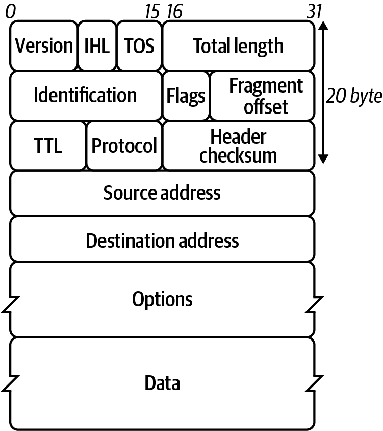
Figure 1-11. IPv4 header format
Let’s look at the header fields in more detail:
Version-
The first header field in the IP packet is the four-bit version field. For IPv4, this is always equal to four.
Internet Header Length(IHL)-
The IPv4 header has a variable size due to the optional 14th field option.
Type of Service-
Originally defined as the type of service (ToS), now Differentiated Services Code Point (DSCP), this field specifies differentiated services. DSC Pallows for routers and networks to make decisions on packet priority during times of congestion. Technologies such as Voice over IP use DSCP to ensure calls take precedence over other traffic.
Total LengthIdentification-
This is the identification field and is used for uniquely identifying the group of fragments of a single IP datagram.
Flags-
This is used to control or identify fragments. In order from most significant to least:
-
bit 0: Reserved, set to zero
-
bit 1: Do not Fragment
-
bit 2: More Fragments
-
Fragment Offset-
This specifies the offset of a distinct fragment relative to the first unfragmented IP packet. The first fragment always has an offset of zero.
Time To Live (TTL)-
An 8-bit time to live field helps prevent datagrams from going in circles on a network.
Protocol-
This is used in the data section of the IP packet. IANA has a list of IP protocol numbers in RFC 790; some well-known protocols are also detailed in Table 1-4.
Table 1-4. IP protocol numbers Protocol number Protocol name Abbreviation 1
Internet Control Message Protocol
ICMP
2
Internet Group Management Protocol
IGMP
6
Transmission Control Protocol
TCP
17
User Datagram Protocol
UDP
41
IPv6 Encapsulation
ENCAP
89
Open Shortest Path First
OSPF
132
Stream Control Transmission Protocol
SCTP
Header Checksum(16-bit)Source address-
This is the IPv4 address of the sender of the packet.
Note
The source address may be changed in transit by a network address translation device; NAT will be discussed later in this chapter and extensively in Chapter 3.
Destination address-
This is the IPv4 address of the receiver of the packet. As with the source address, a NAT device can change the destination IP address.
Options-
The possible options in the header are Copied, Option Class, Option Number, Option Length, and Option Data.
The crucial component here is the address; it’s how networks are identified. They simultaneously identify the host on the network and the whole network itself (more on that in “Getting round the network”). Understanding how to identify an IP address is critical for an engineer. First, we will review IPv4 and then understand the drastic changes in IPv6.
IPv4 addresses are in the dotted-decimal notation for us humans; computers read them out as binary strings. Figure 1-12 details the dotted-decimal notation and binary. Each section is 8 bits in length, with four sections, making the complete length 32 bits. IPv4 addresses have two sections: the first part is the network, and the second is the host’s unique identifier on the network.
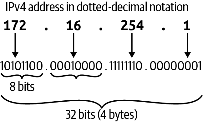
Figure 1-12. IPv4 address
In Example 1-5, we have the output of a computer’s IP address for its network interface
card and we can see its IPv4 address is 192.168.1.2. The IP address also has a subnet mask or netmask
associated with it to make out what network it is assigned. The example’s subnet is netmask 0xffffff00 in
dotted-decimal, which is 255.255.255.0.
Example 1-5. IP address
○ → ifconfig en0 en0:flags=8863<UP,BROADCAST,SMART,RUNNING,SIMPLEX,MULTICAST> mtu 1500options=400<CHANNEL_IO> ether 38:f9:d3:bc:8a:51 inet6 fe80::8f4:bb53:e500:9557%en0 prefixlen64secured scopeid 0x6 inet 192.168.1.2 netmask 0xffffff00 broadcast 192.168.1.255 nd6options=201<PERFORMNUD,DAD> media: autoselect status: active
The subnet brings up the idea of classful addressing. Initially, when an IP address range was assigned, a range was considered to be the combination of an 8-, 16-, or 24-bit network prefix along with a 24-, 16-, or 8-bit host identifier, respectively. Class A had 8 bits for the host, Class B 16, and Class C 24. Following that, Class A had 2 to the power of 16 hosts available, 16,777,216; Class B had 65,536; and Class C had 256. Each class had a host address, the first one in its boundary, and the last one was designated as the broadcast address. Figure 1-13 demonstrates this for us.
Note
There are two other classes, but they are not generally used in IP addressing. Class D addresses are used for IP multicasting, and Class E addresses are reserved for experimental use.
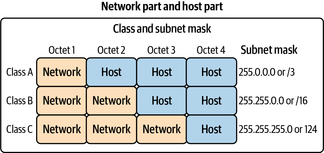
Figure 1-13. IP class
Classful addressing was not scalable on the internet, so to help alleviate that scale issue, we began breaking up the class boundaries using Classless Inter-Domain Routing (CIDR) ranges. Instead of having the full 16 million-plus addresses in a class address range, an internet entity gives only a subsection of that range. This effectively allows network engineers to move the subnet boundary to anywhere inside the class range, giving them more flexibility with CIDR ranges, and helping to scale IP address ranges.
In Figure 1-14, we can see the breakdown of the 208.130.29.33 IPv4 address and the hierarchy that it creates. The 208.128.0.0/11 CIDR range is assigned to ARIN from IANA. ARIN further breaks down the subnet to smaller and smaller subnets for its purposes, leading to the single host on the network 208.130.29.33/32.
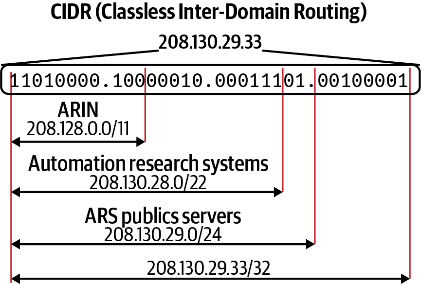
Figure 1-14. CIDR example
Note
The global coordination of the DNS root, IP addressing, and other internet protocol resources is performed by IANA.
Eventually, though, even this practice of using CIDR to extend the range of an IPv4 address led to an exhaustion of address spaces that could be doled out, leading network engineers and IETF to develop the IPv6 standard.
In Figure 1-15, we can see that IPv6, unlike IPv4, uses hexadecimal to shorten addresses for writing purposes. It has similar characteristics to IPv4 in that it has a host and network prefix.
The most significant difference between IPv4 and IPv6 is the size of the address space. IPv4 has 32 bits, while IPv6 has 128 bits to produce its addresses. To put that size differential in perspective, here are those numbers:
IPv4 has 4,294,967,296.
IPv6 has 340,282,366,920,938,463,463,374,607,431,768,211,456.

Figure 1-15. IPv6 address
Now that we understand how an individual host on the network is identified and what network it belongs to, we will explore how those networks exchange information between themselves using routing protocols.
Getting round the network
Packets are addressed, and data is ready to be sent, but how do our packets get from our host on our network to the intended hosted on another network halfway around the world? That is the job of routing. There are several routing protocols, but the internet relies on Border Gateway Protocol (BGP), a dynamic routing protocol used to manage how packets get routed between edge routers on the internet. It is relevant for us because some Kubernetes network implementations use BGP to route cluster network traffic between nodes. Between each node on separate networks is a series of routers.
If we refer to the map of the internet in Figure 1-1, each network on the internet is assigned a BGP autonomous system number (ASN) to designate a single administrative entity or corporation that represents a common and clearly defined routing policy on the internet. BGP and ASNs allows network administrators to maintain control of their internal network routing while announcing and summarizing their routes on the internet. Table 1-5 lists the available ASNs managed by IANA and other regional entities.1
| Number | Bits | Description | Reference |
|---|---|---|---|
0 |
16 |
Reserved |
RFC 1930, RFC 7607 |
1–23455 |
16 |
Public ASNs |
|
23456 |
16 |
Reserved for AS Pool Transition |
RFC 6793 |
23457–64495 |
16 |
Public ASNs |
|
64496–64511 |
16 |
Reserved for use in documentation/sample code |
RFC 5398 |
64512–65534 |
16 |
Reserved for private use |
RFC 1930, RFC 6996 |
65535 |
16 |
Reserved |
RFC 7300 |
65536–65551 |
32 |
Reserved for use in documentation and sample code |
RFC 4893, RFC 5398 |
65552–131071 |
32 |
Reserved |
|
131072–4199999999 |
32 |
Public 32-bit ASNs |
|
4200000000–4294967294 |
32 |
Reserved for private use |
RFC 6996 |
4294967295 |
32 |
Reserved |
RFC 7300 |
In Figure 1-16 ,we have five ASNs, 100–500. A host on 130.10.1.200 wants to reach a host destined on 150.10.2.300. Once the local router or default gateway for the host 130.10.1.200 receives the packet, it will look for the interface and path for 150.10.2.300 that BGP has determined for that route.
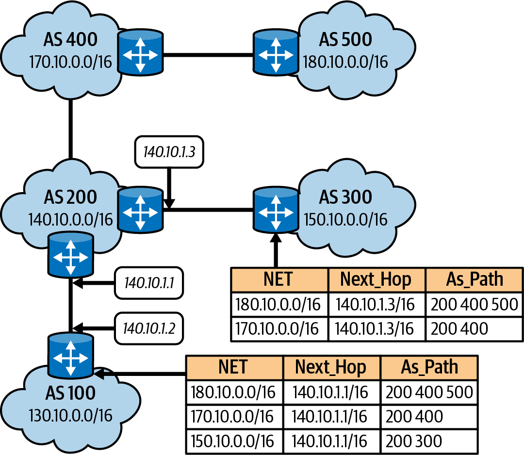
Figure 1-16. BGP routing example
Based on the routing table in Figure 1-17, the router for AS 100 determined the packet belongs to AS 300, and the preferred path is out interface 140.10.1.1. Rinse and repeat on AS 200 until the local router for 150.10.2.300 on AS 300 receives that packet. The flow here is described in Figure 1-6, which shows the TCP/IP data flow between networks. A basic understanding of BGP is needed because some container networking projects, like Calico, use it for routing between nodes; you’ll learn more about this in Chapter 3.
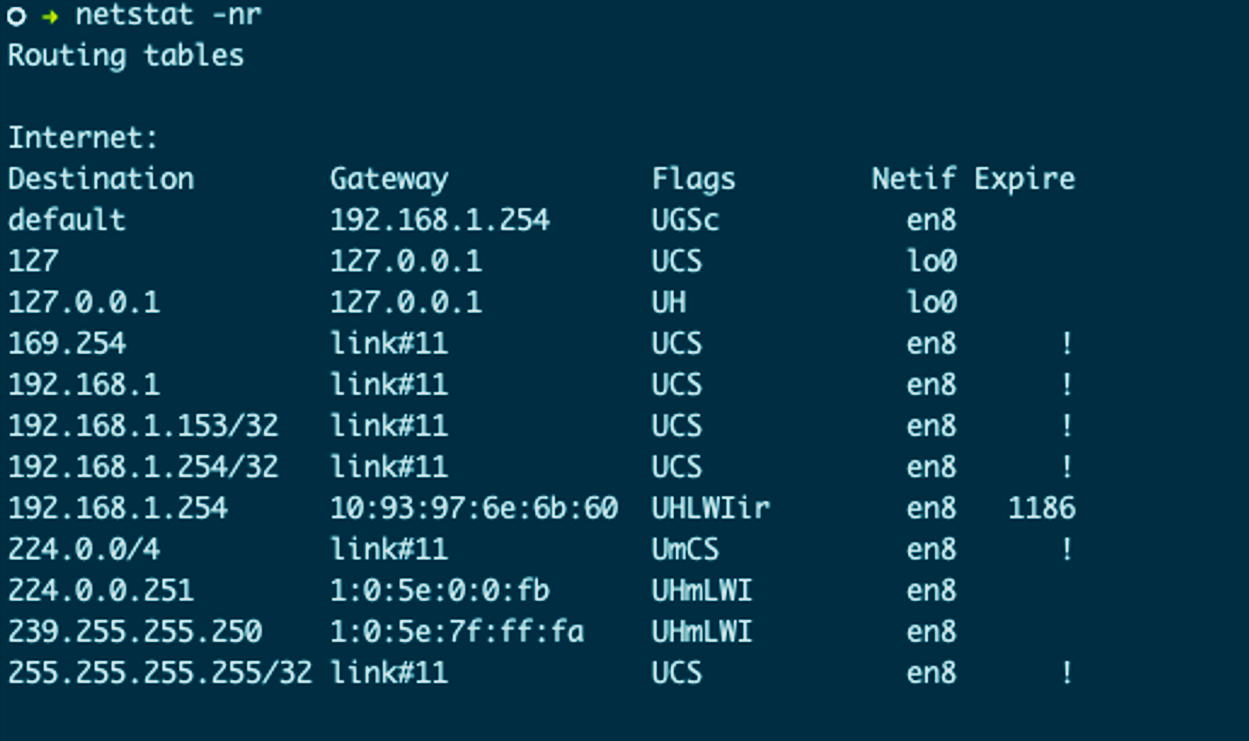
Figure 1-17. Local routing table
Figure 1-17 displays a local route table. In the route table, we can see the interface that a packet will be sent out is based on the destination IP address. For example, a packet destined for 192.168.1.153 will be sent out the link#11 gateway, which is local to the network, and no routing is needed. 192.168.1.254 is the router on the network attached to our internet connection. If the destination network is unknown, it is sent out the default route.
Note
Like all Linux and BSD OSs, you can find more information on netstat’s man page (man netstat). Apple’s netstat is derived from the BSD version. More information can be found in the FreeBSD Handbook.
Routers continuously communicate on the internet, exchanging route information and informing each other of changes on
their respective networks. BGP takes care of a lot of that data exchange, but network engineers and system
administrators can use the ICMP protocol and ping command line tools to test connectivity between hosts and routers.
ICMP
ping is a network utility that uses ICMP for testing connectivity between hosts on the network. In Example 1-6, we
see a successful ping test to 192.168.1.2, with five packets all returning an ICMP echo reply.
Example 1-6. ICMP echo request
○ → ping 192.168.1.2 -c 5 PING 192.168.1.2(192.168.1.2):56data bytes64bytes from 192.168.1.2:icmp_seq=0ttl=64time=0.052 ms64bytes from 192.168.1.2:icmp_seq=1ttl=64time=0.089 ms64bytes from 192.168.1.2:icmp_seq=2ttl=64time=0.142 ms64bytes from 192.168.1.2:icmp_seq=3ttl=64time=0.050 ms64bytes from 192.168.1.2:icmp_seq=4ttl=64time=0.050 ms --- 192.168.1.2 ping statistics ---5packets transmitted,5packets received, 0.0% packet loss round-trip min/avg/max/stddev=0.050/0.077/0.142/0.036 ms
Example 1-7 shows a failed ping attempt that times out trying to reach host 1.2.3.4. Routers and administrators will
use ping for testing connections, and it is useful in testing container connectivity as well. You’ll learn more about this in
Chapters 2 and 3 as we deploy our minimal Golang web server into a container and a pod.
Example 1-7. ICMP echo request failed
○ → ping 1.2.3.4 -c 4 PING 1.2.3.4(1.2.3.4):56data bytes Request timeoutforicmp_seq 0 Request timeoutforicmp_seq 1 Request timeoutforicmp_seq 2 --- 1.2.3.4 ping statistics ---4packets transmitted,0packets received, 100.0% packet loss
As with TCP and UDP, there are headers, data, and options in ICMP packets; they are reviewed here and shown in Figure 1-18:
Type-
ICMP type.
Code-
ICMP subtype.
Checksum-
Internet checksum for error checking, calculated from the ICMP header and data with value 0 substitutes for this field.
Rest of Header(4-byte field)-
Contents vary based on the ICMP type and code.
Data-
ICMP error messages contain a data section that includes a copy of the entire IPv4 header.
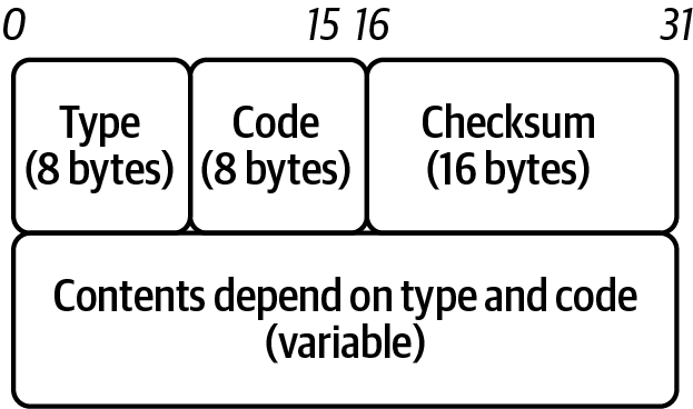
Figure 1-18. ICMP header
Note
Some consider ICMP a Transport layer protocol since it does not use TCP or UDP. Per RFC 792, it defines ICMP, which provides routing, diagnostic, and error functionality for IP. Although ICMP messages are encapsulated within IP datagrams, ICMP processing is considered and is typically implemented as part of the IP layer. ICMP is IP protocol 1, while TCP is 6, and UDP is 17.
The value identifies control messages in the Type field. The code field gives additional context information
for the message. You can find some standard ICMP type numbers in Table 1-6.
| Number | Name | Reference |
|---|---|---|
0 |
Echo reply |
RFC 792 |
3 |
Destination unreachable |
RFC 792 |
5 |
Redirect |
RFC 792 |
8 |
Echo |
RFC 792 |
Now that our packets know which networks they are being sourced and destined to, it is time to start physically sending this data request across the network; this is the responsibility of the Link layer.
Link Layer
The HTTP request has been broken up into segments, addressed for routing across the internet, and now all that is left is to send the data across the wire. The Link layer of the TCP/IP stack comprises two sublayers: the Media Access Control (MAC) sublayer and the Logical Link Control (LLC) sublayer. Together, they perform OSI layers 1 and 2, Data Link and Physical. The Link layer is responsible for connectivity to the local network. The first sublayer, MAC, is responsible for access to the physical medium. The LLC layer has the privilege of managing flow control and multiplexing protocols over the MAC layer to transmit and demultiplexing when receiving, as shown in Figure 1-19. IEEE standard 802.3, Ethernet, defines the protocols for sending and receiving frames to encapsulate IP packets. IEEE 802 is the overarching standard for LLC (802.2), wireless (802.11), and Ethernet/MAC (802.3).
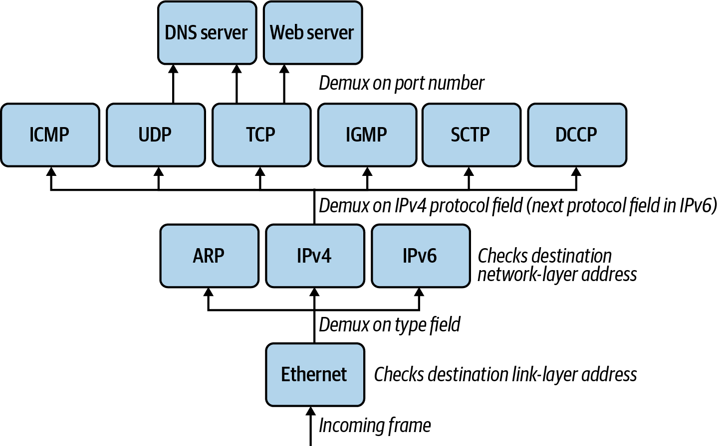
Figure 1-19. Ethernet demultiplexing example
As with the other PDUs, Ethernet has a header and footers, as shown in Figure 1-20.
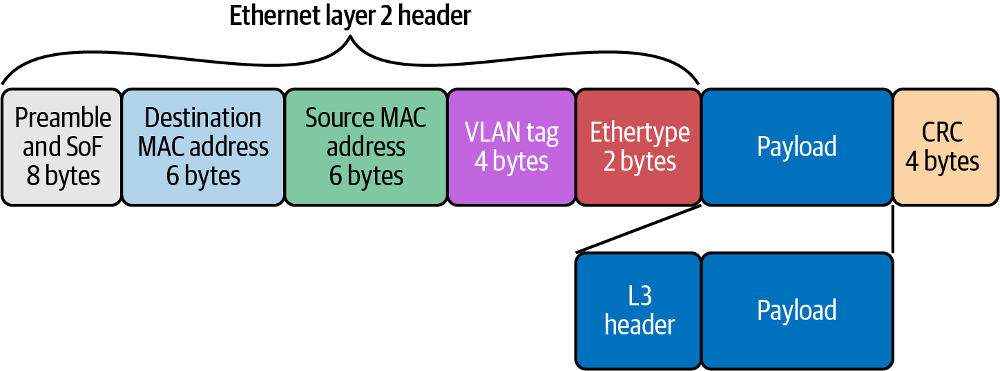
Figure 1-20. Ethernet header and footer
Let’s review these in detail:
Preamble(8 bytes)-
Alternating string of ones and zeros indicate to the receiving host that a frame is incoming.
Destination MAC Address(6 bytes)-
MAC destination address; the Ethernet frame recipient.
Source MAC Address(6 bytes)-
MAC source address; the Ethernet frame source.
VLAN tag(4 bytes)-
Optional 802.1Q tag to differentiate traffic on the network segments.
Ether-type(2 bytes)-
Indicates which protocol is encapsulated in the payload of the frame.
Payload(variable length)-
The encapsulated IP packet.
Frame Check Sequence (FCS)orCycle Redundancy Check (CRC)(4 bytes)-
The frame check sequence (FCS) is a four-octet cyclic redundancy check (CRC) that allows the detection of corrupted data within the entire frame as received on the receiver side. The CRC is part of the Ethernet frame footer.
Figure 1-21 shows that MAC addresses get assigned to network interface hardware at the time of manufacture. MAC addresses have two parts: the organization unit identifier (OUI) and the NIC-specific parts.
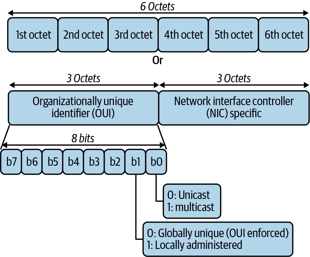
Figure 1-21. MAC address
The frame indicates to the recipient of the Network layer packet type. Table 1-7 details the common protocols handled. In Kubernetes, we are mostly interested in IPv4 and ARP packets. IPv6 has recently been introduced to Kubernetes in the 1.19 release.
| EtherType | Protocol |
|---|---|
0x0800 |
Internet Protocol version 4 (IPv4) |
0x0806 |
Address Resolution Protocol (ARP) |
0x8035 |
Reverse Address Resolution Protocol (RARP) |
0x86DD |
Internet Protocol version 6 (IPv6) |
0x88E5 |
MAC security (IEEE 802.1AE) |
0x9100 |
VLAN-tagged (IEEE 802.1Q) frame with double tagging |
When an IP packet reaches its destination network, the destination IP address is resolved with the Address Resolution Protocol for IPv4 (Neighbor Discovery Protocol in the case of IPv6) into the destination host’s MAC address. The Address Resolution Protocol must manage address translation from internet addresses to Link layer addresses on Ethernet networks. The ARP table is for fast lookups for those known hosts, so it does not have to send an ARP request for every frame the host wants to send out. Example 1-8 shows the output of a local ARP table. All devices on the network keep a cache of ARP addresses for this purpose.
Example 1-8. ARP table
○ → arp -a ?(192.168.0.1)at bc:a5:11:f1:5d:be on en0 ifscope[ethernet]?(192.168.0.17)at 38:f9:d3:bc:8a:51 on en0 ifscope permanent[ethernet]?(192.168.0.255)at ff:ff:ff:ff:ff:ff on en0 ifscope[ethernet]?(224.0.0.251)at 1:0:5e:0:0:fb on en0 ifscope permanent[ethernet]?(239.255.255.250)at 1:0:5e:7f:ff:fa on en0 ifscope permanent[ethernet]
Figure 1-22 shows the exchange between hosts on the local network. The browser makes an HTTP request for a website
hosted by the target server. Through DNS, it determines that the server has the IP address 10.0.0.1. To continue
to send the HTTP request, it also requires the server’s MAC address. First, the requesting computer consults a cached ARP
table to look up 10.0.0.1 for any existing records of the server’s MAC address. If the MAC address is found, it sends an
Ethernet frame with the destination address of the server’s MAC address, containing the IP packet addressed to 10.0.0.1 onto
the link. If the cache did not produce a hit for 10.0.0.2, the requesting computer must send a broadcast ARP request
message with a destination MAC address of FF:FF:FF:FF:FF:FF, which is accepted by all hosts on the local network,
requesting an answer for 10.0.0.1. The server responds with an ARP response message containing its MAC and IP address. As part of answering the request, the server may insert an entry for requesting the computer’s MAC address into its ARP table
for future use. The requesting computer receives and caches the response information in its ARP table and can now send
the HTTP packets.
This also brings up a crucial concept on the local networks, broadcast domains. All packets on the broadcast domain receive all the ARP messages from hosts. In addition, all frames are sent all nodes on the broadcast, and the host compares the destination MAC address to its own. It will discard frames not destined for itself. As hosts on the network grow, so too does the broadcast traffic.

Figure 1-22. ARP request
We can use tcpdump to view all the ARP requests happening on the local network as in
Example 1-9. The packet capture details the ARP packets; the Ethernet type used, Ethernet (len 6); and the
higher-level protocol, IPv4. It also includes who is requesting the MAC address of the IP address, Request who-has 192.168.0.1 tell 192.168.0.12.
Example 1-9. ARP tcpdump
○ → sudo tcpdump -i en0 arp -vvv tcpdump: listening on en0, link-type EN10MB(Ethernet), capture size262144bytes 17:26:25.906401 ARP, Ethernet(len 6), IPv4(len 4), Request who-has 192.168.0.1 tell 192.168.0.12, length 46 17:26:27.954867 ARP, Ethernet(len 6), IPv4(len 4), Request who-has 192.168.0.1 tell 192.168.0.12, length 46 17:26:29.797714 ARP, Ethernet(len 6), IPv4(len 4), Request who-has 192.168.0.1 tell 192.168.0.12, length 46 17:26:31.845838 ARP, Ethernet(len 6), IPv4(len 4), Request who-has 192.168.0.1 tell 192.168.0.12, length 46 17:26:33.897299 ARP, Ethernet(len 6), IPv4(len 4), Request who-has 192.168.0.1 tell 192.168.0.12, length 46 17:26:35.942221 ARP, Ethernet(len 6), IPv4(len 4), Request who-has 192.168.0.1 tell 192.168.0.12, length 46 17:26:37.785585 ARP, Ethernet(len 6), IPv4(len 4), Request who-has 192.168.0.1 tell 192.168.0.12, length 46 17:26:39.628958 ARP, Ethernet(len 6), IPv4(len 4), Request who-has 192.168.0.1 tell 192.168.0.13, length 28 17:26:39.833697 ARP, Ethernet(len 6), IPv4(len 4), Request who-has 192.168.0.1 tell 192.168.0.12, length 46 17:26:41.881322 ARP, Ethernet(len 6), IPv4(len 4), Request who-has 192.168.0.1 tell 192.168.0.12, length 46 17:26:43.929320 ARP, Ethernet(len 6), IPv4(len 4), Request who-has 192.168.0.1 tell 192.168.0.12, length 46 17:26:45.977691 ARP, Ethernet(len 6), IPv4(len 4), Request who-has 192.168.0.1 tell 192.168.0.12, length 46 17:26:47.820597 ARP, Ethernet(len 6), IPv4(len 4), Request who-has 192.168.0.1 tell 192.168.0.12, length 46 ^C13packets captured233packets received by filter0packets dropped by kernel
To further segment the layer 2 network, network engineers can use virtual local area network (VLAN) tagging. Inside the Ethernet frame header is an optional VLAN tag that differentiates traffic on the LAN. It is useful to use VLANs to break up LANs and manage networks on the same switch or different ones across the network campus. Routers between VLANs filter broadcast traffic, enable network security, and alleviate network congestion. They are useful to the network administrator for those purposes, but Kubernetes network administrators can use the extended version of the VLAN technology known as a virtual extensible LAN (VXLAN).
Figure 1-23 shows how a VXLAN is an extension of a VLAN that allows network engineers to encapsulate layer 2 frames into layer 4 UDP packets. A VXLAN increases scalability up to 16 million logical networks and allows for layer 2 adjacency across IP networks. This technology is used in Kubernetes networks to produce overlay networks, which you’ll learn more about in later chapters.
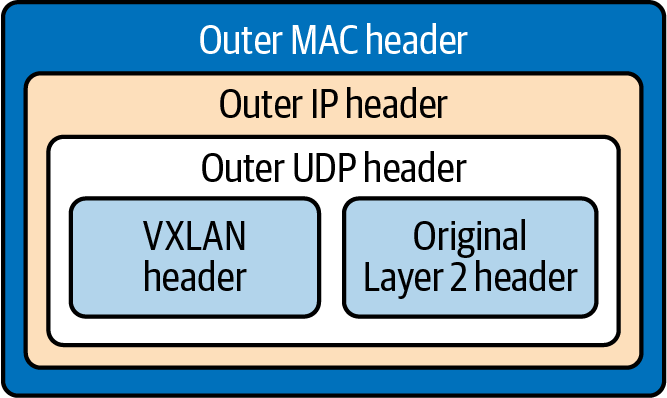
Figure 1-23. VXLAN packet
Ethernet also details the specifications for the medium to transmit frames on, such as twisted pair, coaxial cable, optical fiber, wireless, or other transmission media yet to be invented, such as the gamma-ray network that powers the Philotic Parallax Instantaneous Communicator.2 Ethernet even defines the encoding and signaling protocols used on the wire; this is out of scope for our proposes.
The Link layer has multiple other protocols involved from a network perspective. Like the layers discussed previously, we have only touched the surface of the Link layer. We constrained this book to those details needed for a base understanding of the Link layer for the Kubernetes networking model.
Revisiting Our Web Server
Our journey through all the layers of TCP/IP is complete. Figure 1-24 outlines all the headers and footers each layer of the TCP/IP model produces to send data across the internet.
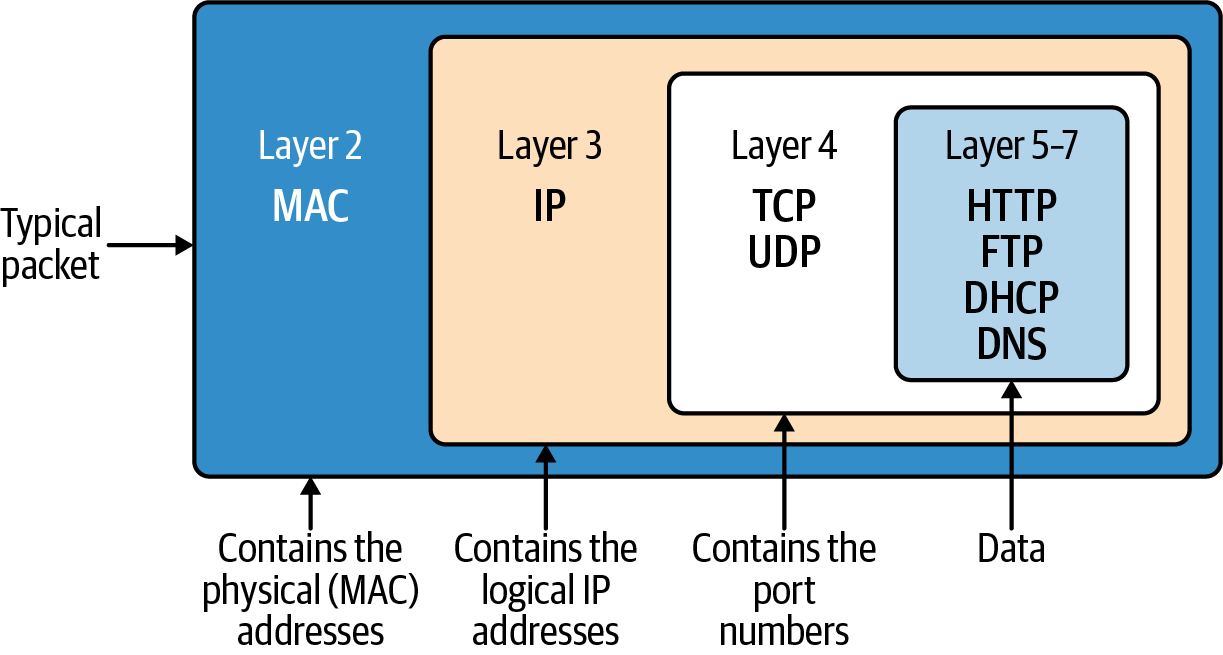
Figure 1-24. TCP/IP PDU full view
Let’s review the journey and remind ourselves again what is going on now that we understand each layer in detail. Example 1-10 shows our web server again, and Example 1-11 shows the cURL request for it from earlier in the chapter.
Example 1-10. Minimal web server in Go
packagemainimport("fmt""net/http")funchello(whttp.ResponseWriter,_*http.Request){fmt.Fprintf(w,"Hello")}funcmain(){http.HandleFunc("/",hello)http.ListenAndServe("0.0.0.0:8080",nil)}
Example 1-11. Client request
○ → curl localhost:8080 -vvv * Trying ::1... * TCP_NODELAYset* Connected to localhost(::1)port 8080 > GET / HTTP/1.1 > Host: localhost:8080 > User-Agent: curl/7.64.1 > Accept: */* > < HTTP/1.1200OK < Date: Sat,25Jul202014:57:46 GMT < Content-Length: 5 < Content-Type: text/plain;charset=utf-8 < * Connection#0 to host localhost left intactHello* Closing connection 0
We begin with the web server waiting for a connection in Example 1-10. cURL requests the HTTP server at 0.0.0.0 on port
8080. cURL determines the IP address and port number from the URL and proceeds to establish a TCP connection to the
server. Once the connection is set up, via a TCP handshake, cURL sends the HTTP request. When the web server
starts up, a socket of 8080 is created on the HTTP server, which matches TCP port 8080; the same is done
on the cURL client side with a random port number. Next, this information is sent to the Network layer, where
the source and destination IP addresses are attached to the packet’s IP header. At the client’s Data Link layer, the source
MAC address of the NIC is added to the Ethernet frame. If the destination MAC address is unknown, an ARP request is
made to find it. Next, the NIC is used to transmit the Ethernet frames to the web server.
When the web server receives the request, it creates packets of data that contain the HTTP response. The packets are
sent back to the cURL process by routing them through the internet using the source IP address
on the request packet. Once received by the cURL process, the packet is sent from the device to the drivers. At
the Data Link layer, the MAC address is removed. At the Network Protocol layer, the IP address is verified and
then removed from the packet. For this reason, if an application requires access to the client IP, it needs to be
stored at the Application layer; the best example here is in HTTP requests and the X-Forwarded-For header. Now the socket
is determined from the TCP data and removed. The packet is then forwarded to the client application that creates that
socket. The client reads it and processes the response data. In this case, the socket ID was random, corresponding to
the cURL process. All packets are sent to cURL and pieced together into one HTTP response. If we were to use the -O
output option, it would have been saved to a file; otherwise, cURL outputs the response to the terminal’s standard out.
Whew, that is a mouthful, 50 pages and 50 years of networking condensed into two paragraphs! The basics of networking we have reviewed are just the beginning but are required knowledge if you want to run Kubernetes clusters and networks at scale.
Conclusion
The HTTP transactions modeled in this chapter happen every millisecond, globally, all day on the internet and data center network. This is the type of scale that the Kubernetes networks’ APIs help developers abstract away into simple YAML. Understanding the scale of the problem is our first in step in mastering the management of a Kubernetes network. By taking our simple example of the Golang web server and learning the first principles of networking, you can begin to wrangle the packets flowing into and out of your clusters.
So far, we have covered the following:
-
History of networking
-
OSI model
-
TCP/IP
Throughout this chapter, we discussed many things related to networks but only those needed to learn about using the Kubernetes abstractions. There are several O’Reilly books about TCP/IP; TCP/IP Network Administration by Craig Hunt (O’Reilly) is a great in-depth read on all aspects of TCP.
We discussed how networking evolved, walked through the OSI model, translated it to the TCP/IP stack, and with that stack completed an example HTTP request. In the next chapter, we will walk through how this is implemented for the client and server with Linux networking.
1 “Autonomous System (AS) Numbers”. IANA.org. 2018-12-07. Retrieved 2018-12-31.
2 In the movie Ender’s Game, they use the Ansible network to communicate across the galaxy instantly. Philotic Parallax Instantaneous Communicator is the official name of the Ansible network.
Get Networking and Kubernetes now with the O’Reilly learning platform.
O’Reilly members experience books, live events, courses curated by job role, and more from O’Reilly and nearly 200 top publishers.

