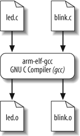
In this section, we show an example build procedure for the Arcom VIPER-Lite development board. If another hardware platform is used, a similar process should be followed using the tools and conventions that accompany that hardware.
The installation procedure for the software development tools is provided in Appendix B. Once the tools are installed, the commands covered in the following sections are entered into a command shell. For Windows users, the command shell is a Cygwin bash shell (Cygwin is a Unix environment for Windows); for Linux users, it is a regular command shell.
Tip
In this and subsequent chapters, commands entered in a shell
environment are indicated by the number sign (#)
prompt. Commands entered in the RedBoot environment are indicated by
the RedBoot prompt (RedBoot>).
We will next take a look at the individual commands in order to manually perform the three separate tasks (compiling, linking, and locating) described earlier in this chapter. Then we will learn how to automate the build procedure with makefiles.
As we have implemented it, the Blinking LED example consists of two source modules: led.c and blink.c. The first step in the build process is to compile these two files. The basic structure for the gcc compiler command is:
arm-elf-gcc []options...file
The command-line options weâll need are:
-gTo generate debugging info in default format
-cTo compile and assemble but not link
-WallTo enable most warning messages
-I../includeTo look in the directory include for header files
Here are the actual commands for compiling the C source files:
#arm-elf-gcc âg -c âWall -I../include led.c#arm-elf-gcc -g âc -Wall -I../include blink.c
We broke up the compilation step into two separate commands, but you can compile the two files with one command. To use a single command, just put both of the source files after the options. If you wanted different options for one of the source files, you would need to compile it separately as just shown. For additional information about compiler options, take a look at http://gcc.gnu.org.
Running these commands will be a good way to verify that the tools were set up properly. The result of each of these commands is the creation of an object file that has the same prefix as the .c file, and the extension .o. So if all goes well, there will now be two additional filesâled.o and blink.oâin the working directory. The compilation procedure is shown in Figure 4-3.
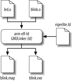
We now have the two object filesâled.o and blink.oâthat we need in order to perform the second step in the build process. As we discussed earlier, the GNU linker performs the linking and locating of the object files.
For the third step, locating, there is a linker script file named viperlite.ld that we input to ld in order to establish the location of each section in the Arcom boardâs memory. The basic structure for the linker and locater ld command is:
arm-elf-ld []options...file
The command-line options weâll need for this step are:
- -Map blink.map
To generate a map file and use the given filename
- -T viperlite.ld
To read the linker script
- -N
To set the text and data sections to be readable and writable
- -o blink.exe
To set the output filename (if this option is not included, ld will use the default output filename a.out)
The actual command for linking and locating is:
# arm-elf-ld âMap blink.map âT viperlite.ld -N âo blink.exe led.o blink.oThe order of the object files determines their placement in memory. Because we are not linking in any startup code, the order of the object files is irrelevant. If startup code were included, you would want that object file to be located at the proper address. The linker script file can be used to specify where you want the startup routine (and other code) to reside in memory. Furthermore, you can also use the linker script file to specify exact addresses for code or data, should you find it necessary to do so.
As you can see in this command, the two object filesâled.o and blink.oâare the last arguments on the command line for linking. The linker script file, viperlite.ld, is also passed in for locating the data and code in the Arcom boardâs memory. The result of this command is the creation of two filesâblink.map and blink.exeâin the working directory. The linking and locating procedure is shown in Figure 4-4.
The .map file gives a complete listing of all code and data addresses for the final software image. If you have never seen such a map file before, be sure to take a look at this one before reading on. It provides information similar to the contents of the linker script described earlier. However, these are results rather than instructions and therefore include the actual lengths of the sections and the names and locations of the public symbols found in the relocatable program. Weâll see later how this file can be used as a debugging aid.
The last step of the previous section creates an image of the Blinking LED program that we can load onto the Arcom board. In certain cases, you might need to format the image from the build procedure for your specific target platform.
One tool included with the GNU toolset that can assist with formatting images is the strip utility, which is part of the binary utilities package called binutils (pronounced âbin-you-tillsâ). The strip utility can remove particular sections from an object file. The basic command structure for the strip utility is:
arm-elf-strip []options... [input-file]-o output-file
The build procedure for subsequent chapters in the book generates two executable files: one with debug information and one without. The executable that contains the debug information includes dbg in its filename. The debug image should be used with gdb. If an image is downloaded with RedBoot, the nondebug image should be used.
The command used to strip symbol information is:
# arm-elf-strip --remove-section=.comment blinkdbg.exe -o blink.exeThis removes the section named .comment from the image blinkdbg.exe and creates the new output
file blink.exe.
There might be another time when you need an image file that can be burned into ROM or flash. The GNU toolset has just what you need for this task. The utility objcopy (object copy) is able to copy the contents of one object file into another object file. The basic structure for the objcopy utility is:
arm-elf-objcopy []options[input-file]output-file
For example, letâs suppose we want to convert our Blinking LED program from ELF format into an Intel Hex Format file. [4] The command line we use for this is:
# arm-elf-objcopy -O ihex blink.exe blink.hexThis command uses the âO ihex option to generate an Intel Hex Format file. The input file is blink.exe (the objcopy utility determines the input file type). Finally, the output file is named blink.hex.
Warning
If no output filename is given, the strip and objcopy utilities overwrite the original input file with the generated file.
Some of the other GNU tools are useful for providing other information about the image you have built. For example, the size utility, which is part of the binutils package, lists the section sizes and total size for a given object file. Here is the command for using the size utility:
# arm-elf-size blink.exeThe resulting output is:
text    data     bss     dec     hex filename
 328       0       0     328     148 blink.exe
The top row consists of column headings and shows the sections
text, data, and bss. The Blinking LED program contains 328
bytes in the text section, no bytes
in the data section, and no bytes
in the bss section. The dec column shows the total image size in
decimal, and the hex column shows
it in hexadecimal (decimal 328 = hexadecimal 0x148). These total sizes
are in bytes. The last column, filename, contains the filename of the
object file.
You will notice that the size of the section, 328 bytes, is much smaller than the approximately 3 KB file size of our blink.exe. This is because debugging information is located also in the blink.exe file.
Additional information about the other GNU binutils can be found online at http://www.gnu.org.
Weâre now ready to download the program to our development board, which weâll do in the next chapter. To wrap up our discussion of building programs, letâs take a quick look at another useful tool in the build process.
[4] Intel Hex format is an ASCII file format devised by Intel for storing and downloading binary images.
Get Programming Embedded Systems, 2nd Edition now with the O’Reilly learning platform.
O’Reilly members experience books, live events, courses curated by job role, and more from O’Reilly and nearly 200 top publishers.


