2.19. SIMULATION DIAGRAMS
From the development of signal-flow graphs, Mason’s theorem, and operational amplifiers, we can now develop simulation diagrams. The simulation diagram can be either a block diagram or a signal-flow graph which is constructed to have a specified transfer function or to model a set of specified differential equations. The resulting simulation diagram is very useful because it can be used to construct either a digital computer or analog computer simulation of the control system.
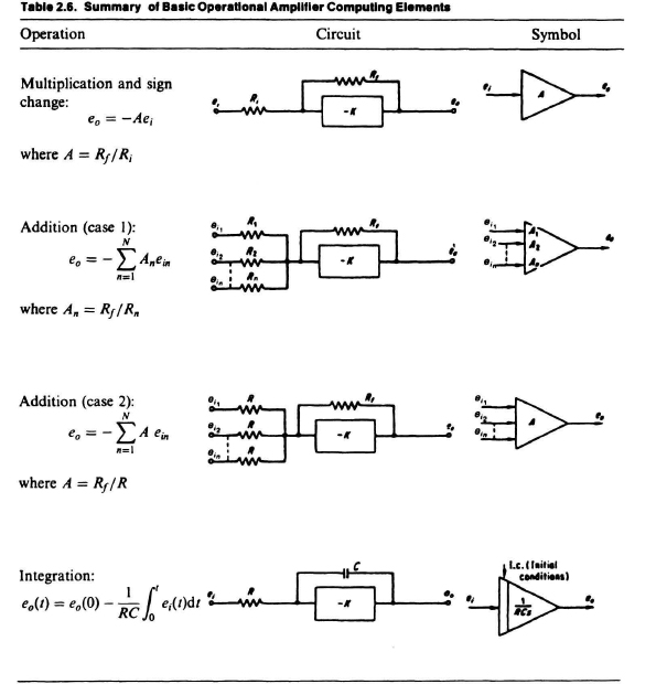
From the previous section on operational amplifiers, the basic element of the simulation diagram is an integrator (see Eq. (2.143) and Table 2.6). In using the integrator in a simulation diagram, therefore, it is important to recognize that if the output of the integrator is x(t), then the input to the integrator is dx(t)/dt. Similarly, if two integrators are connected in cascade and the output of the last integrator is x(t), then the input to the last integrator is dx(t)/dt, and the input to the first integrator is d2x(t)/dt2. We can use integrators, amplifiers, and summers, which were all described in Section 2.18 on operational amplifiers and summarized in Table 2.6, to represent a given differential equation by a simulation diagram.
In addition to representing a differential equation by a simulation diagram, we can reverse this procedure and start with a given transfer function ...
Get Modern Control System Theory and Design, 2nd Edition now with the O’Reilly learning platform.
O’Reilly members experience books, live events, courses curated by job role, and more from O’Reilly and nearly 200 top publishers.

