7.3 MULTIPLEXERS
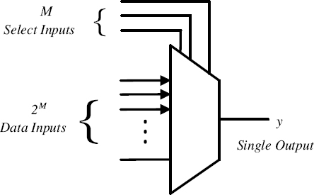
A multiplexer (or “mux”) is a digital switch that has 2M data inputs, M select (control) inputs, and a single output. It routes data from one of 2M data inputs to its single output. Figure 7.2 shows the graphical symbol of a 2M : 1 (pronounced “2M to 1”) multiplexer. The select input lines control which data input is connected to the output. Thus, a multiplexer acts as a programmable digital switch.
7.3.1 2: 1 Multiplexer
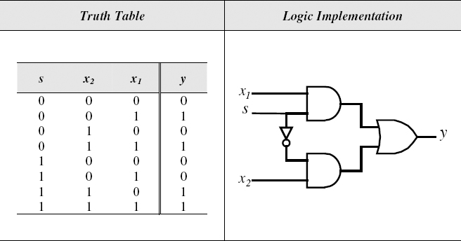
A 2: 1 multiplexer has two data inputs, one select input, and a single output. The function of a 2: 1 multiplexer is described by the truth table shown in Figure 7.3. The figure also shows the logic implementation of the 2 : 1 multiplexer. The same circuit can be realized using transmission gates, as described in Section 3.9. The VHDL code, which implements a 2: 1 multiplexer, is illustrated in Figure 7.4. The clause with–select–when is used as a select signal assignment to switch between the two inputs.

Figure 7.2 Graphical Symbol of a 2M: 1 Multiplexer

Figure 7.3 2:1 Multiplexer

Figure 7.4 VHDL Code for a 2: 1 Multiplexer Using Select Signal Assignment
Figure 7.5 VHDL Code for a 2: 1 Multiplexer Using Conditional Signal Assignment
A second VHDL ...
Get Introduction to Digital Systems: Modeling, Synthesis, and Simulation Using VHDL now with the O’Reilly learning platform.
O’Reilly members experience books, live events, courses curated by job role, and more from O’Reilly and nearly 200 top publishers.

