Chapter 4. Logical Components: The Building Blocks
Ready to start creating an architecture? It’s not as easy as it sounds—and if you don’t do it correctly, your software system could come crumbling to the ground, just like a poorly designed skyscraper or bridge.
In this chapter we’ll show you several approaches for identifying and creating logical components, the functional building blocks of a system that describe how its pieces all fit together. Using the techniques described in this chapter will help you to create a solid architecture—a foundation upon which you can build a successful software system.
Put on your hard hat and gloves, get your tools ready, and let’s get started.
Logical components revisited
Logical components are one of the dimensions of software architecture. They are the functional building blocks of a system that make up what is known as the problem domain. In Chapter 1 you learned a bit about them, and in this chapter we’ll dive deep into what logical components are and how to create them.
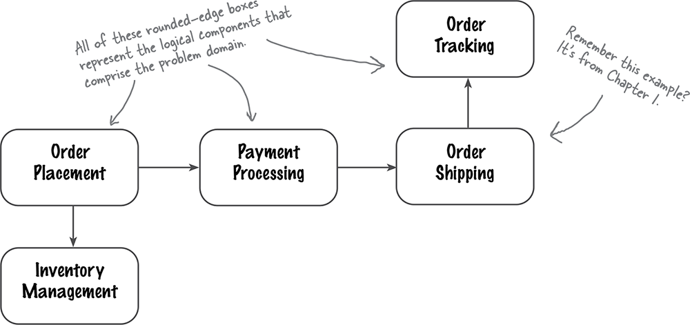
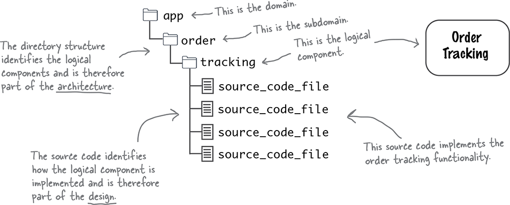
Remember that, in most programming languages, logical components are represented through the directory structure of your source code repository. For example, source code located in the app/order/tracking directory would be contained within a logical component named Order Tracking.
Adventurous Auctions goes online
Want to go on a safari in Tanzania? Observe wildlife in the Galapagos Islands? Hike to the base camp of Mount Everest? Adventurous Auctions is here to help!
You’ve probably seen our ads or attended some of our live auctions around the country. These kinds of adventures are hard to come by and can take years to reserve; our company auctions them off at a significant cost savings.
We want more people around the world to be able to access these great trips, so we’re taking our adventurous auctions online (in addition to our in-person auctions).
That’s where you come in: we need a new system to support the online auctions of our adventurous trips.


Here’s what the new system needs to do:
Include both in-person and online bids in every auction.
Scale up to meet demand, so hundreds or even thousands of people can participate in each auction.
Allow online users to register with Adventurous Auctions and provide us with their credit card details so they can pay if they win a trip.
Allow online users to view live video streams of in-person auctions, as well as all bids placed so far, both in person and online.
Allow online users to bid on trips, just like the people in the room.
Determine which online bidder bids the asking price first (this is called “winning the bid”). If an online bidder bids at the same time as an in-person bidder, the auctioneer then determines who bid first.
When the auctioneer announces an online user as the winner, the system charges the winner’s credit card, notifies the winner, then moves on to the next trip in the auction.
Note
Pay attention, because we’re going to show you how to create a logical architecture for this system.
Logical versus physical architecture
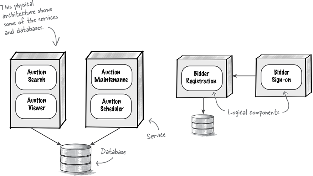
A logical architecture shows all of the logical building blocks of a system and how they interact with each other (known as coupling). A physical architecture, on the other hand, shows things like the architectural style, services, protocols, databases, user interfaces, API gateways, and so on.
Note
We’re going to be talking a lot about component coupling later in this chapter.
The logical architecture of a system is independent of the physical architecture—meaning the logical architecture doesn’t care about databases, services, protocols, and so on. Let’s look at an example of what we mean by a logical architecture.
As you remember, Adventurous Auctions needs to create and schedule online auctions and allow bidders to register, search for auctions, and view the trips that are up for bid. Here are some of the components—the functional building blocks—that will help make that happen.

See how the logical architecture doesn’t include the various components of physical architecture mentioned above? It’s a different view of the system. To see what we mean, compare the diagram above with the following physical architecture diagram. Notice how the physical architecture associates services with components from the logical architecture, and also shows the services and databases for the system.
Creating a logical architecture
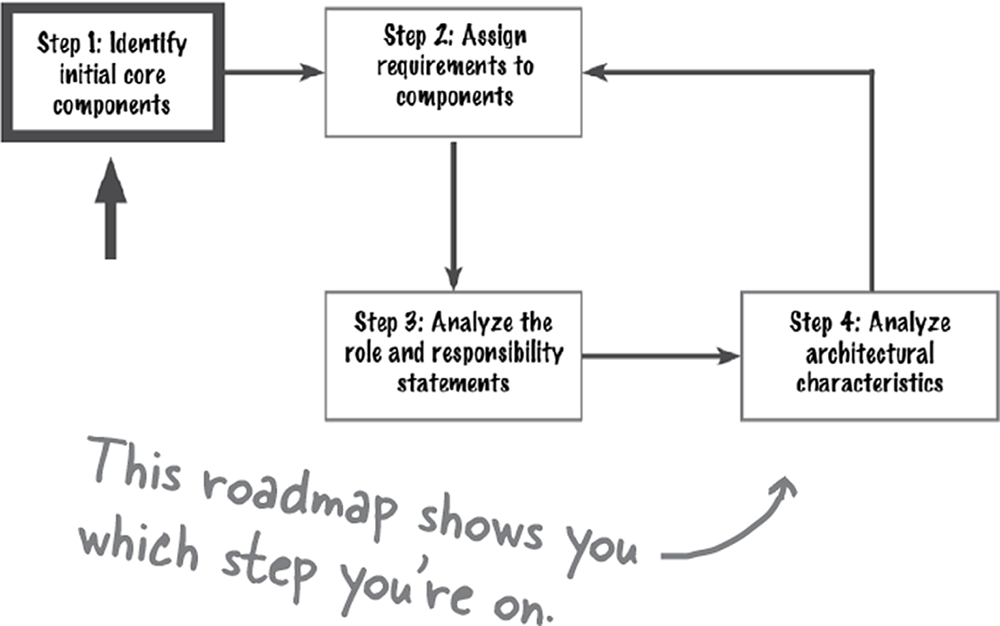
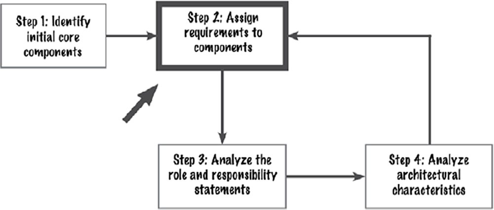
Identifying logical components isn’t as easy as it sounds. To help, we’ve created this flowchart. Don’t worry—we’ll be covering all of these steps in detail in the following pages.
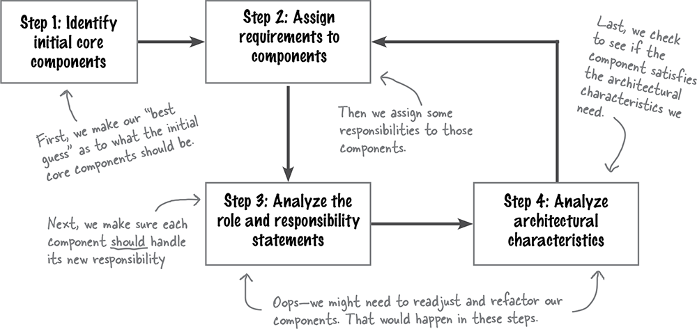
This flow continues as long as the system is alive.
This flowchart shows a series of steps to begin greenfield applications (new systems created from scratch) and perform ongoing maintenance on existing ones.
Ever wonder why it’s so common for a well-designed system to end up as an unmaintainable mess in no time? It’s because teams don’t pay enough attention to the logical architecture of their systems.
Anytime you make a change or add a new feature to the system, you should always go through each of these steps to ensure that the logical components are the right size and are doing what they are meant to do.
Step 1: Identifying initial core components
The first step in creating a logical architecture is identifying the initial core components. Many times this is purely a guessing game, and you’ll likely refactor the components you initially identify into others. So don’t spend a lot of time worrying about how big or small your components are—we’ll get to that. First, let’s show you what we mean by a “guessing game.”

Given this simple description, you can start out by creating three logical components, one for each of the three major things the system does.

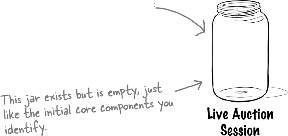
These components aren’t really doing anything yet. You see, we’ve identified the initial components, but we haven’t assigned them any responsibility yet. You could think of them as empty jars. They represent our initial best guess, based on a major action that takes place in the system. That’s why we call them initial core components.

Yes, there is! In fact, you can use several approaches to remove some of the guesswork.
You don’t know a lot of details about the system or its requirements yet, and the components you initially identify are likely to change as you learn more. That’s why we say it’s a guessing game at this stage—and that’s perfectly okay!
We’ll show you two common approaches for identifying initial core components: the workflow approach and the actor/action approach.
There are other approaches that may seem like good ideas initially but that can lead you down a very bad path. We’ll discuss those after we show you the good stuff.
Workflow approach
The workflow approach is an effective way to identify an initial set of core components by thinking about the major workflows of the system—in other words, the journey a user might take through the system. Don’t worry about capturing every step; start out with the major processing steps, and then work your way down to more details.
Note
You can model different workflows to create even more initial components.
Let’s use the workflow approach to identify some initial core components for the Adventurous Auctions architecture.

Names matter.
Pay close attention to how you name your initial core components. A good name should succinctly describe what that component does.

Actor/action approach
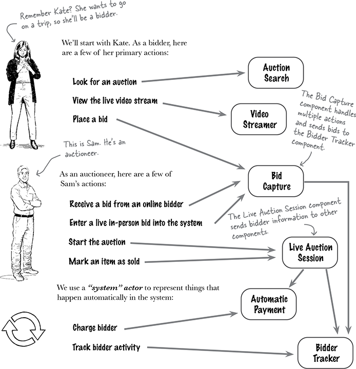
The actor/action approach is particularly helpful if you have multiple actors (users) in the system. You start by identifying the various actors. Then, you identify some of the primary actions they might take and assign each action to a new or existing component.
Returning to our Adventurous Auctions example, let’s use the actor/action approach to identify some initial core components.
The entity trap
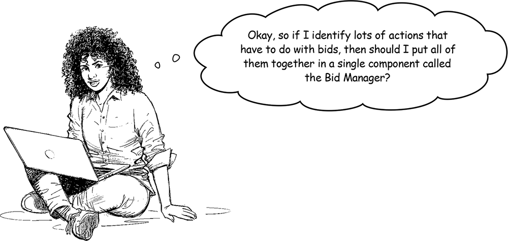
We call this approach the entity trap because it’s very easy to fall into it when identifying the initial core logical components, and you’ll run into lots of issues if you do this.
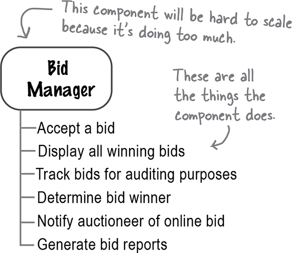
First of all, the name “Bid Manager” is too vague. Can you tell what the component does just by looking at the name? Neither can we. A name like this doesn’t tell us enough about the component’s role and responsibilities.
Second, the component has too many responsibilities. All too often, components in the entity trap become convenient dumping grounds for all functionality related to those entities. As a result, they take on too much responsibility and become too big and difficult to maintain, scale, and make fault tolerant.
Note
Pro Tip

Watch out for words like manager or supervisor when naming your logical components—those are good indicators that you might be in the entity trap.
Step 2: Assign requirements
Once you’ve identified some initial core components, it’s time to move on to the next step: assigning requirements to those logical components.
In this step, you’ll take functional user stories or requirements and figure out which component should be responsible for each one. Remember, each component is represented by a directory structure. Your source code resides in that directory, so it contains that requirement.
Let’s go back to the initial set of components we defined based on what Frank (the CIO) said about the basic workflow of Adventurous Auctions. Now it’s time to assign some responsibilities to these components.
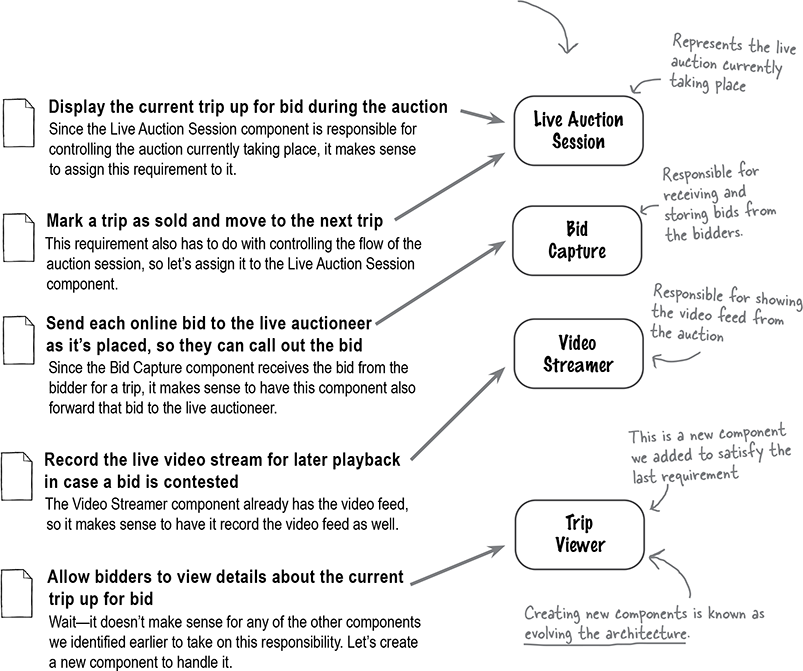
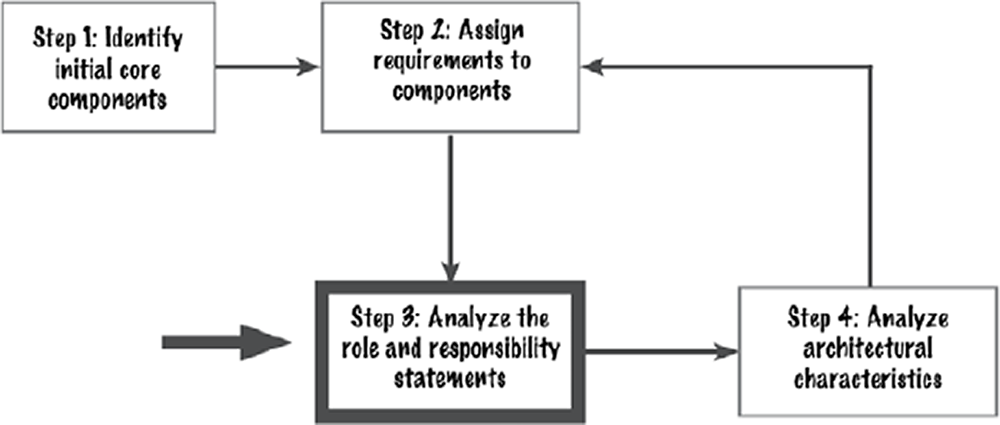
Step 3: Analyze roles and responsibilities
As you start assigning functionality (in other words, user stories or requirements) to logical components, the roles and responsibilities of each component will start to naturally grow. The purpose of this step is to make sure that the component to which you are assigning functionality should actually be responsible for that functionality and that it doesn’t end up doing too much.
Let’s say we create a component called Live Auction Session that has the following responsibilities during a live auction:
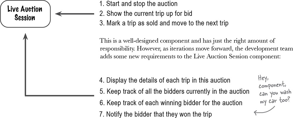
With this added functionality, this component is now taking on too much responsibility. This is a common situation, so don’t be surprised if it happens to you. When it does, don’t panic—that’s what this step is here for. Let’s see if we can fix this situation by moving some of the responsibility of the Live Auction Session component to other components.
Note
If you’ve ever had too much on your plate at work, you likely gave some of that work to others. Do the same with components—offload some of the responsibility to someone else.
Sticking to cohesion
When you analyze a component’s role and responsibility statement or set of operations, check to see if the functionality is closely related. This is known as cohesion: the degree and manner to which the operations of a component are interrelated. Cohesion is a useful tool for making sure a component has the right responsibilities.
When analyzing the role and responsibilities of a component, it’s common to find an outlier (an odd piece of functionality) or a component that is doing too much. In these cases, it’s usually a good idea to shift some of the responsibility to other components.
Now it’s your turn to fix the Live Auction Session component.
Step 4: Analyze characteristics
The final step in identifying initial core components is to verify that each component aligns with the driving architectural characteristics that are critical for success. In most cases this involves breaking apart a component for better scalability, elasticity, or availability, but it could also involve putting components together if their functionalities are tightly coupled.
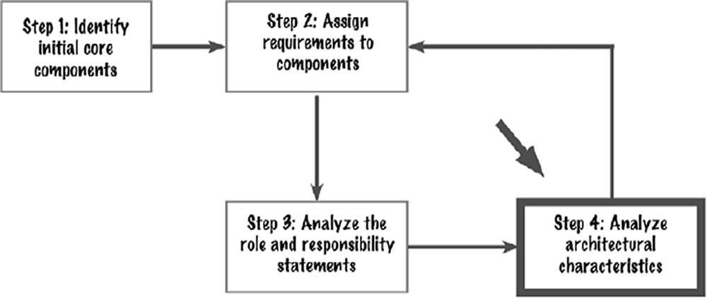
Let’s look once again at our Adventurous Auctions example. We previously identified a Bid Capture component that is responsible for accepting bids, storing all bids in a Bid Tracker database, and forwarding the highest bid to the auctioneer. Here is the overall flow for the Bid Capture component:
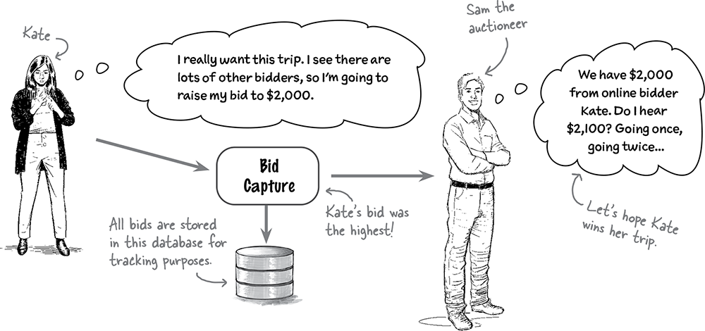
This architecture looks good, but just to be sure, we should make sure the Bid Capture component supports the system’s critical architectural characteristics (those that are important for success).
We know the system has to support thousands of bidders per second—that’s scalability. We also know the system must be up and running while auctions are taking place—that’s availability. Finally, the system must accept a bid and get it to the auctioneer as fast as possible—that’s performance.
Note
These are all important to the success of Adventurous Auctions.
Now it’s your turn to analyze the Bid Capture component against these critical architectural characteristics.
These are the critical architectural characteristics for Adventurous Auctions:
Scalability: The system has to support thousands of bidders per second
Availability: The system must be up and running while the auctions are taking place
Performance: The system must accept a bid and get it to the auctioneer as fast as possible.
Hints (things to consider):
What if the database goes down?
Can the database keep up with the volume of inserts based on the bids coming in?
Will inserts into the database be fast enough to get the bids to the auctioneer?
Consider the actions the Bid Capture component has to take upon receiving a bid.
Note
Use this area to draw how you might change the Bid Capture component based on the critical architectural characteristics and considerations above.
The Bid Capture component
Let’s work through this exercise by reviewing the current responsibilities of the Bid Capture component:
Accept bids from online bidders and from the auctioneer for live bidders.
Determine which online bid is the highest.
Write all bids to a Bid Tracker database for tracking purposes.
Notify the auctioneer of the highest bid.
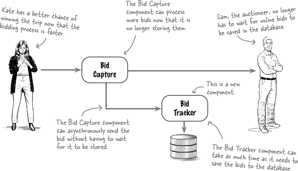
It makes sense for the Bid Capture component to write the bids to the database, since it has them. But database connections and throughput are limited, so having Bid Capture do this significantly impacts scalability. It also impacts performance by adding wait time for writing the data to the database, as well as availability if the database were ever to go down.
Note
This is what we mean by analyzing characteristics.
If we assign the last requirement to a new component called Bid Tracker, we can significantly increase the scalability, performance, and availability of the Bid Capture component. That lets the system process more bids faster and get the highest bid to the auctioneer as quickly as possible. The Bid Capture component can send the bids to the Bid Tracker and won’t have to wait for the bid to be written to the database.
Note
You might break apart or combine components in this step, based on the architectural characteristics needed.
Component coupling

Yes, and this is the right time to do it.
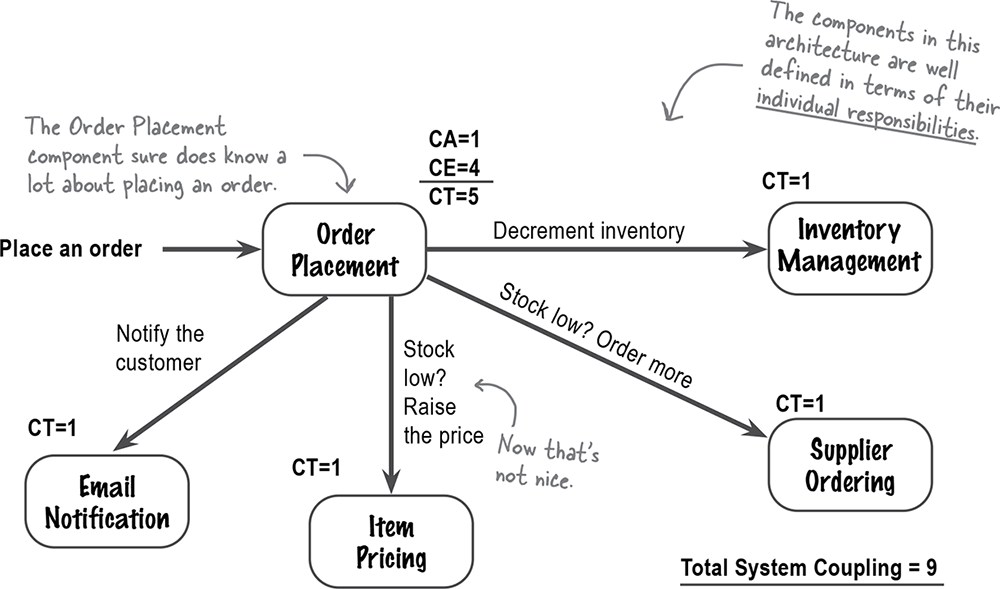
As you identify the initial core components, it’s important to determine how they interact. This is known as component coupling: the degree to which components know about and rely on each other. The more the components interact, the more tightly coupled the system is and the harder it will be to maintain.
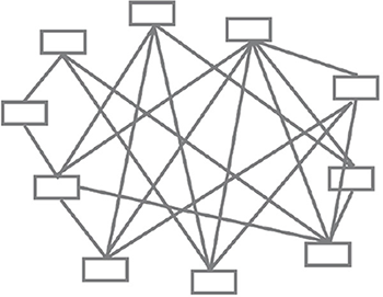
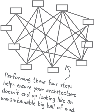
Remember this diagram from several pages ago? It’s called a “big ball of mud” because there are so many component interactions and dependencies that the diagram starts to look like a ball of mud (or maybe like a bowl of spaghetti).
That’s why it’s so important to pay attention to how components interact and what dependencies exist between them.
You need to be concerned about two types of coupling when creating logical components: afferent coupling and efferent coupling. Don’t be concerned if you’ve never heard these formal terms before—we’re going to explain them in the following pages.
Afferent coupling
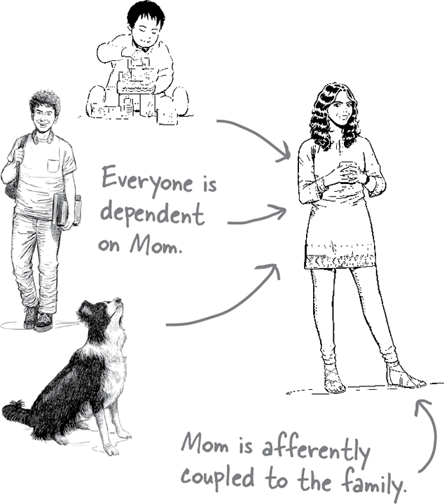
Children depend on their parents for a lot of things, like making sure they have plenty of food to eat and a safe place to live, driving them to soccer practice, or even giving them an allowance so they can buy candy or a really cool comic book. As it turns out, parents are afferently coupled to their children, and even to the family dog, because all of them depend on the parents for something.
Afferent coupling is the degree and manner to which other components are dependent on some target component (in this case, Mom). It’s sometimes referred to as fan-in, or incoming, coupling. In most code analysis tools, it’s simply denoted as CA.
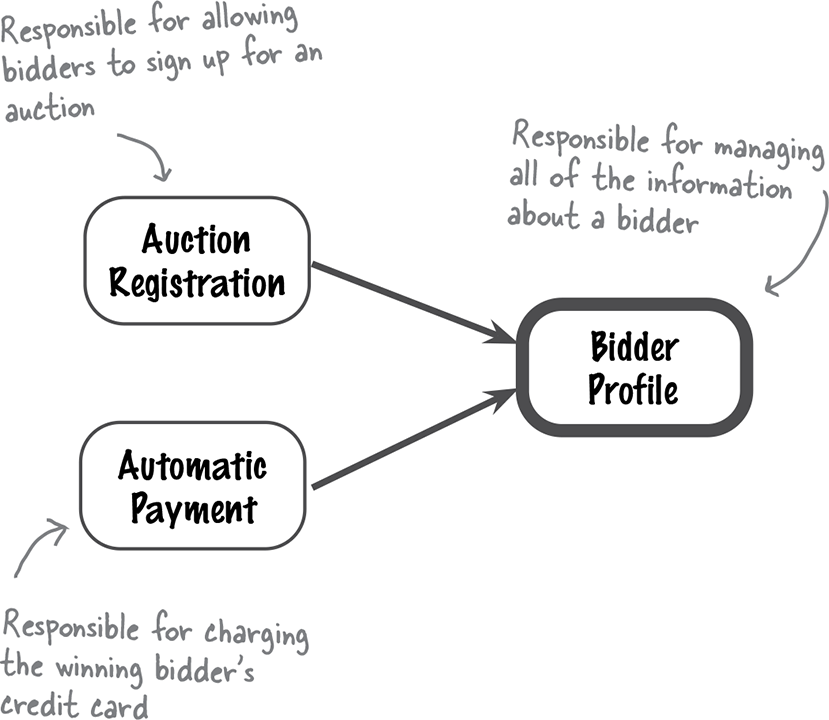
To see how afferent coupling works, look at the interaction between three of the logical components within the Adventurous Auctions logical architecture on the left.
Both the Auction Registration component and the Automatic Payment component depend on the Bidder Profile component to return bidder profile information. In this scenario, the Bidder Profile component has an afferent coupling level of 2, because two components depend on it to complete their work.
Efferent coupling
Now let’s look at things from a young child’s point of view. As a child, you might have been dependent not only on your parents, but also your teachers, friends, classmates, and so on. Being dependent on others is known as efferent coupling.
Efferent coupling is exactly the opposite of afferent coupling, and it’s measured by the number of components on which a target component depends. It’s also known as fan-out coupling or outgoing coupling. In static source code analysis tools, it’s usually denoted as CE.
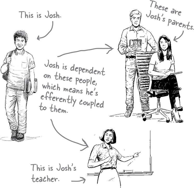
So, what does efferent coupling look like with logical components? Let’s take a look at Adventurous Auctions again, this time considering the process of accepting a bid from Kate for a trip.
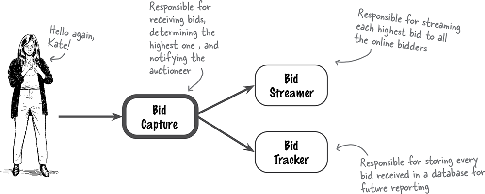
Because the Bid Capture component depends on the Bid Streamer and Bid Tracker components to process a bid, it is efferently coupled to these components. It has an efferent coupling level of 2 (in other words, it’s dependent on two other components).
Measuring coupling
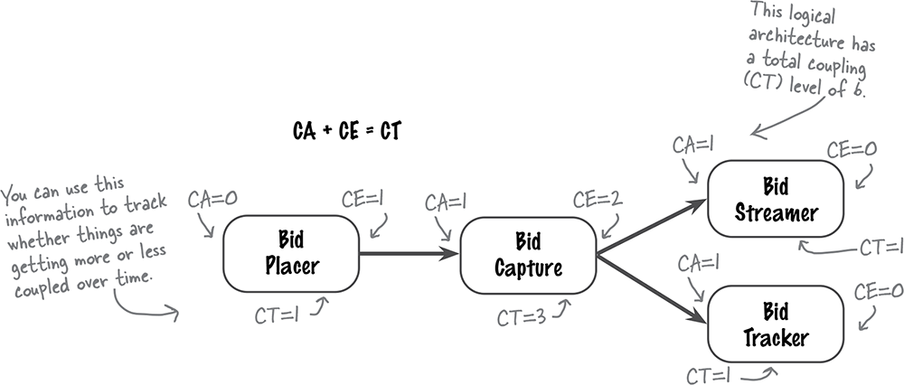
You can measure a particular component’s amount of coupling in three ways: by considering its total afferent coupling (CA), its total efferent coupling (CE), and its total coupling (CT), or the sum of the total afferent and efferent coupling. These measurements tell you which components have the highest and lowest coupling, as well as the entire system’s overall coupling level.

Great question. Developers are taught to strive for loosely coupled systems, but not how to do it. We’ll show you how by introducing a technique called the Law of Demeter.
The Law of Demeter, also known as the Principle of Least Knowledge, is named after Demeter, the Greek goddess of agriculture. She produced all grain for mortals to use, but she had no knowledge of what they did with the grain. Because of this, Demeter was loosely coupled to the mortal world.
Logical components work in the same way. The more knowledge a component has about other components and what needs to happen in the system, the more coupled it is to those components. By reducing its knowledge of other components, we reduce that component’s level of coupling.
On the next few pages, we’ll show you more about the Law of Demeter and how it can be used to decouple systems.
Applying the Law of Demeter
The total system coupling level didn’t bother us that much. What does bother us is how tightly coupled the Order Placement component is (CT=5), how unbalanced the component coupling is, and how much knowledge the Order Placement component has about the order placement process.
Note
The Order Placement component is taking charge.
Let’s apply the Law of Demeter to fix these problems by moving the “low stock” knowledge to the Inventory Management component.
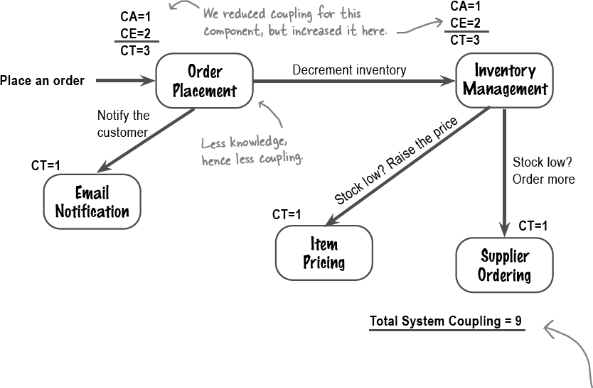
By moving the knowledge of actions to take for a “low stock” condition to Inventory Management, we reduced the amount of knowledge about the system, and hence the coupling, of the Order Placement component However, we increased the knowledge of the Inventory Management component, and thus increased its coupling. This is what the Law of Demeter is all about—less knowledge, less coupling; more knowledge, more coupling.
Note
Coupling is all about how much knowledge components have about the rest of the system.
A balancing act
Do you remember the First Law of Software Architecture? Here it is again (because it’s so important):
Everything in software architecture is a trade-off.
Loose coupling is no exception. Let’s compare the two architectures we’ve just seen and analyze their trade-offs.
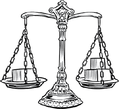
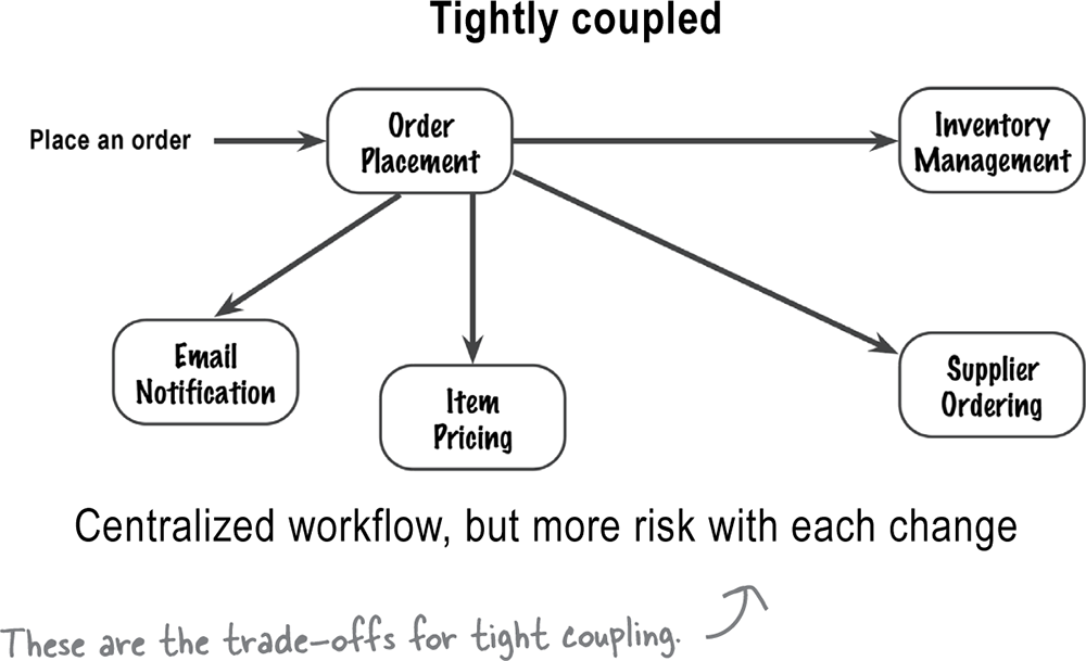
With the tightly coupled architecture, if you want to know what happens when a customer places an order, you only have to look at the Order Placement component to understand the workflow.
However, changing the Item Pricing and Supplier Ordering components will no longer affect the Order Placement component.
With loose coupling, you distribute the knowledge about what needs to happen, so that no one component knows all the steps. If you want to understand the workflow of placing an order, you have to go to multiple components to get the full picture.
However, in this case, the Order Placement component is dependent on four other components. If any one of those components changes, it could break the Order Placement component.
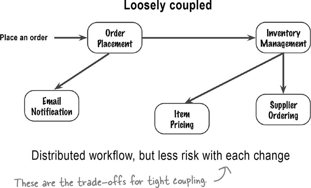
Two components are coupled if a change in one component might cause a change in the other component.
Note
This is a good rule to remember.
Some final words about components
Congratulations! Now that you can identify logical components and the dependencies between them, you’re on your way to creating a software architecture. We know this was a long chapter, but it’s also an important one. Thinking about a system as a collection of logical components helps you, as an architect, better understand its overall structure and how it works.
In the next part of your software architectural journey, you’ll be focusing on the technical details of the system—things like architecture styles, services, databases, and communication protocols. But before you go, review the following bullet points to make sure you fully understand everything about logical components.
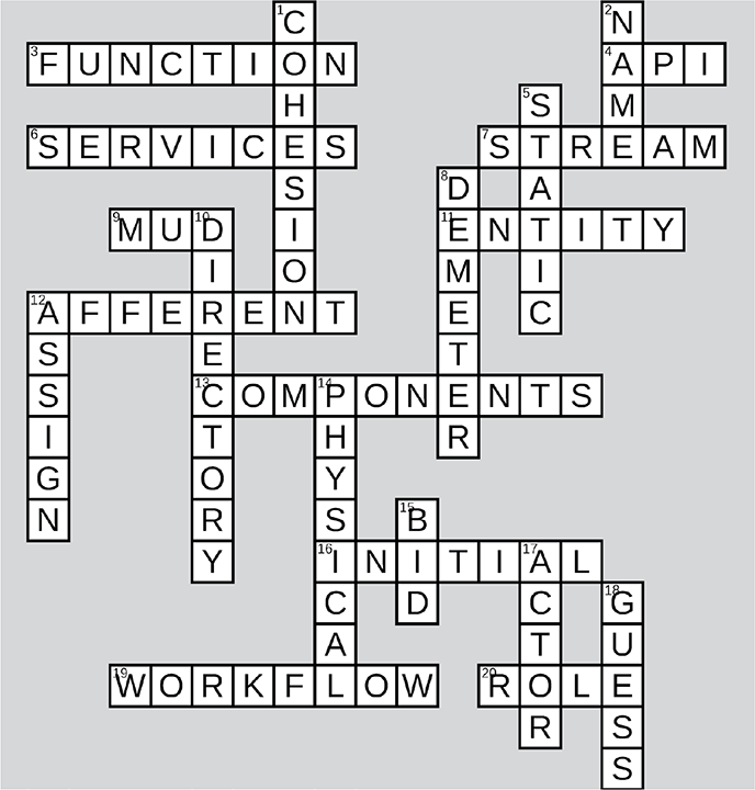
Logical Components Crossword

Now’s your chance to have a little fun and see how much knowledge you’ve gained. See if you can fill in this crossword puzzle with clues about logical components.
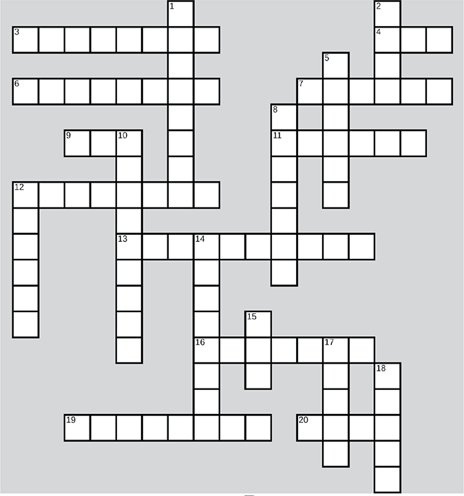
Across
3. Each component performs a _____
4. _____ gateways appear in a physical architecture but not a logical one
6. A physical architecture associates _____ with components
7. One system component might be a live video _____
9. Avoid building a big ball of _____
11. Be sure to avoid the _____ trap
12. Coupling might be _____ or efferent
13. Logical _____ are the functional building blocks of a system
16. Early on, you’ll identify _____ core components
19. A user’s journey through the system is called their _____
20. Each logical component has a _____ and a responsibility
Down
1. A component’s _____ is about how interrelated its operations are
2. Give each component a descriptive _____
5. Afferent and efferent coupling are both forms of _____ coupling
8. The Principle of Least Knowledge is also called the Law of _____
10. A good place to look for components is the codebase’s _____ structure
12. Step 2 is to _____ requirements to logical components
14. An architecture diagram can show the logical or _____ architecture
15. Adventurous Auctions lets users _____ on trips
17. You can identify components with an _____/action approach
18. Identifying logical components may involve taking your best _____
![]() Solution in “Logical Components Crossword Solution”
Solution in “Logical Components Crossword Solution”
From “Exercise”
From “Who Does What?”
From “Exercise”
From “Exercise”
From “Make it Stick”
From “Test Drive”
Get Head First Software Architecture now with the O’Reilly learning platform.
O’Reilly members experience books, live events, courses curated by job role, and more from O’Reilly and nearly 200 top publishers.
