The Hartley Oscillator
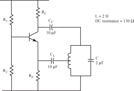
25 Figure 9.27 shows a Hartley oscillator circuit. In this type of circuit, the feedback is taken from a tap on the coil, or from a connection between two inductors.
Capacitor CL stops the emitter DC voltage from being pulled down to 0 volts through the coil. CL should have a reactance of less than RE/10, or less than 160 ohms at the oscillator frequency.
Work through the following calculations:
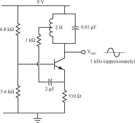
Figure 9.28 shows a Hartley oscillator with the parallel LC circuit connected between the collector and the supply voltage. As with the circuit shown in Figure 9.27, this circuit provides a feedback signal to the emitter from a tap in the coil, in the correct phase to provide positive feedback.
Objective
Get Complete Electronics Self-Teaching Guide with Projects now with the O’Reilly learning platform.
O’Reilly members experience books, live events, courses curated by job role, and more from O’Reilly and nearly 200 top publishers.


