7Block Diagrams
The reason for using Laplace transforms is to convert differential equations into algebraic equations. The point of this chapter is to convert these algebraic equations into a block diagram representation, which will be the starting point for the design of feedback controllers for these systems as shown in Chapters 9 and 10.
7.1 Block Diagram for a DC Motor
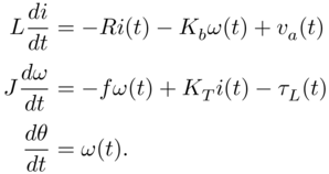
A DC motor servo (positioning) system typically consists of a DC motor, an amplifier and sensors for position and current. The interest here is to understand how to model this system in the ![]() domain for control purposes. Recall the dynamic equations of the DC motor given as
domain for control purposes. Recall the dynamic equations of the DC motor given as

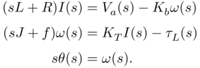
Let's take the Laplace transform of the DC machine equations (7.1) with zero initial conditions to obtain

After some rearrangement we have

A block diagram of these equations is given in Figure 7.1 on the next page and is simply a graphical way to illustrate the relationships between the Laplace transform variables.

Get An Introduction to System Modeling and Control now with the O’Reilly learning platform.
O’Reilly members experience books, live events, courses curated by job role, and more from O’Reilly and nearly 200 top publishers.

