9Tracking and Disturbance Rejection
9.1 Servomechanism
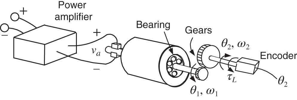
Before developing tracking and disturbance rejection feedback controllers, we first review how a physical system described by a differential equation model is abstracted to a block diagram. In this and following chapters, feedback controllers will be developed using such block diagram models so it is important to keep in mind where they come from and what they represent. Specifically, consider a servomechanism (servo system) used for positioning applications such as robot arms and machine tools. The physical hardware consists of a servomotor (DC motor in our case), power amplifier, and a position sensor (encoder) as shown in Figure 9.1. A schematic diagram of a complete servomechanism is given in Figure 9.2 including a simple proportional feedback controller.

Figure 9.1 DC motor, power amplifier, gears. and encoder of a servo system.
Note that the encoder (position sensor) is on the output shaft rather than the motor shaft. This simple controller does the following: The position of the output shaft ![]() (
(![]() ) is obtained from the encoder1 and is subtracted from the desired (reference) position . This difference is called the error. ...
) is obtained from the encoder1 and is subtracted from the desired (reference) position . This difference is called the error. ...
Get An Introduction to System Modeling and Control now with the O’Reilly learning platform.
O’Reilly members experience books, live events, courses curated by job role, and more from O’Reilly and nearly 200 top publishers.

