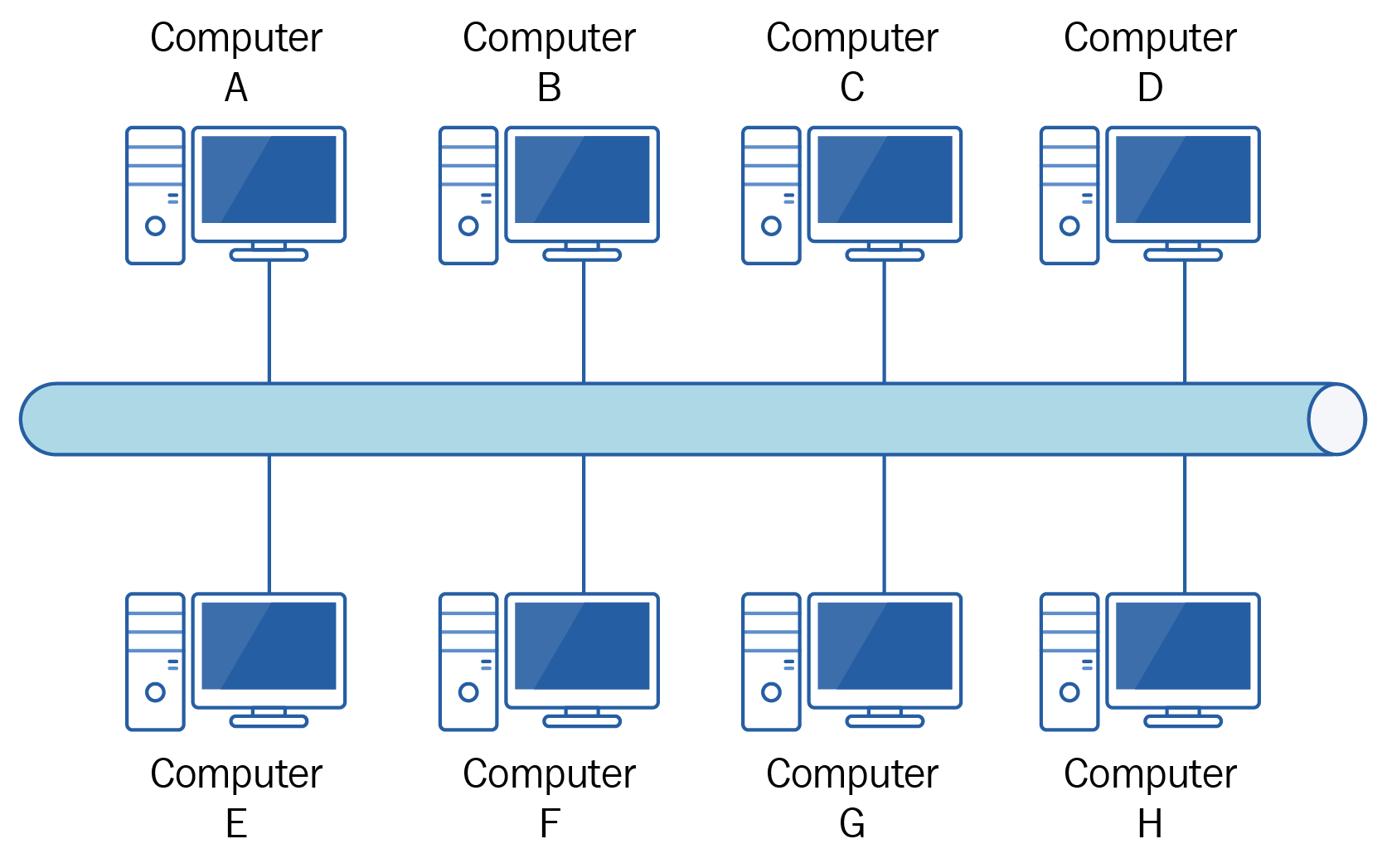
For clarity I'm going to draw the bus topology in a way that in some implementations could be classed as slightly inaccurate, but I will explain why afterward. A bus topology can generally be described as a backbone cable with devices connected directly to it, as shown in Figure 5.1:

In the preceding diagram, I want to draw your attention to two things. Firstly, the backbone is quite clearly one single cable, and in some cases this would be correct, but in some others you might find it is made up of a number of shorter cables. Secondly, the various computers connecting to the backbone are shown as doing ...

