2.2 ELECTROCHEMICAL ENERGY: FUNDAMENTALS OF GALVANIC CELLS
AND SUPERCAPACITORS
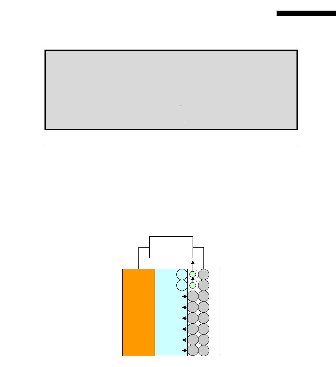
A galvanic cell, in its simplest form, consists of two metal electrodes separated by a layer of elec-
trolyte, which allows for ion transport between the electrodes (Fig. 2.2.1). The right (negative) metal
electrode in Figure 2.2.1 loses its atoms, e.g. Li or Zn, which are converted into ions (through an
electrochemical reaction), e.g. Li
þ
,Zn
2þ
,Al
3þ
, as they go into solution. The electrode becomes
negatively charged, due to excess electrons that flow through the external connection. Thus, in the
galvanic cell, ‘atomic fuel’ is consumed at the negative electrode to produce electricity: For every 1–2
electrons that flow through the external circuit, a metal atom must go into the electrolyte solution as
BOX 2.3 GEOMETRIC RELATIONS IN SOLIDS
Atomic density – Number of atoms per unit of volume (e.g. per cm
3
):
n
at
¼ n
3D
¼ n
Number of atoms per unit of length in an arbitrary direction (e.g. per cm):
n
1D
w
ffiffiffiffiffiffiffiffi
n
3D
3
p
Nearest-neighbor distance:
l
aa
wn
1
3
Surface concentration – Number of atoms per unit of area in an arbitrary cross-section (e.g. per cm
2
):
n
s
¼ n
2D
wn
2
3
positive electrode
electrolyte
M
M
M
M
M
M
M
negative electrode
M
+
M
+
M
M
M
M
M
M
M
External
Load
e
-
e
-
FIGURE 2.2.1
Schematic diagram of a galvanic cell
2.2 Electrochemical energy: Fundamentals of galvanic cells and supercapacitors 17
a positively charged ion M
þ
. When the supply of the metal fuel atoms is exhausted, the galvanic cell
can no longer provide energy.
2.2.1 Energy stored in the galvanic cell
Because the typical chemical bonding energy per electron is on the order of a few eV, the typical
potential difference V produced by such a system is w 1 Volt. Thus, one atom of the atomic fuel
produces energy
3
w eV and the total stored energy E
stored
can be estimated as
E
stored
¼ 3N
at
¼ eN
el
,N
at
,VweN
at
,V (2.2.1)
where e is the charge on an electron, N
el
is the number of electrons released per atom, and N
at
is the
number of atoms comprising the metal electrode.
The upper bound for the energy in an electrochemical source can be estimated by using the fact that
the number of molecules (or atoms) in one mole of matter is given by Avogadro’s Number, N
A
¼6.02
10
23
at/mol, and that the atomic density in all solids, n
at,
varies from 10
22
to 10
23
at/cm
3
:
E
max
we,N
A
,ð1VÞ¼1:6 10
19
,6:02 10
23
w10
5
J
mole
(2.2.2a)
or
E
max
we,n
at
,ð1VÞ¼1:6 10
19
,10
23
w10
4
J
cm
3
(2.2.2b)
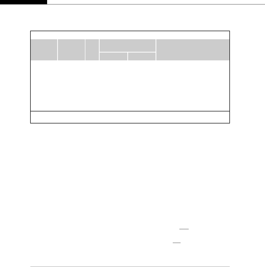
In Table 2.2.1 , the gravimetric (J/g) and volumetric (J/cm
3
) electrochemical energy densities for
several metal electrodes are characterized.
Table 2.2.1 Electrochemical energy density metrics for several metals
Negative
electrode
1
reaction
Electrode
potential
(V)* N
el
Characteristic energy
density metrics**
ReferenceJ/cm
3
J/g
Al
3þ
/ Al –1.68 3 4.86E þ 04 1.80E þ 04 [1-3]
Mg
2þ
/ Mg –2.38 2 3.33E þ 04 1.91E þ 04 [3]
Mn
2þ
/Mn –1.18 2 3.07E þ 04 4.13E þ 03 [1]
Ti
2þ
/Ti –1.63 2 2.94E þ 04 6.54E þ 03 [4]
Li
þ
/Li –3.05 1 2.23E þ 04 4.20E þ 04 Commercial lithium batteries
Zn
2þ
/Zn –0.76 2 1.61E þ 04 2.25E þ 03 Commercial zinc-carbon batteries
Fe
2þ
/Fe –0.44 2 1.19E þ 04 1.51E þ 03 Ni-Fe
Cd
2þ
/Cd –0.40 2 5.95E þ 03 6.88E þ 02 Commercial nickel-cadmium batteries
*
Electrode potential vs. the standard hydrogen electrode.
**
Calculated using formulas in Box 2.2.
1
The electrochemical community refers to the ‘negative electrode’ as the ‘anode’ and the positive electrode as the ‘cathode.’
However, physicists and electrical engineers use an inverted notation. Because of conflicting conventions for anode and
cathode usage and because this paper primarily targets an audience beyond the professional electrochemical community,
the terms ‘positive electrode’ and ‘negative electrode’ are used.
18 CHAPTER 2 Energy in the small: Integrated micro-scale energy sources
Get Microsystems for Bioelectronics now with the O’Reilly learning platform.
O’Reilly members experience books, live events, courses curated by job role, and more from O’Reilly and nearly 200 top publishers.

