APPENDIX C
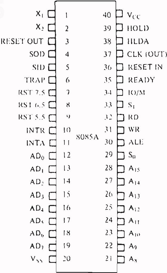
Figure C.1 shows 8085 pins and signals. The following table describes the function of each pin:
SYMBOL |
FUNCTION |
|---|---|
A15 (Output, Three-Stale) |
Address Bus: The most significant 8 bits of the memory address or the 8 bils of the I/O address. |
A0–7 (Input/Output, Tree-State) |
Multiplexed address/data bus: Lower 8-bits of the memory address (or I/O address) appear on the bus during the first clock cycle (T state) of a machine cycle. It then becomes the data bus during the second and third clock cycles. |
: (Output) |
Address Latch Enable: It occurs during the first clock state of a machine cycle and ... |
Get Microprocessors and Microcomputer-Based System Design, 2nd Edition now with the O’Reilly learning platform.
O’Reilly members experience books, live events, courses curated by job role, and more from O’Reilly and nearly 200 top publishers.

