85
4.9 I/O architecture
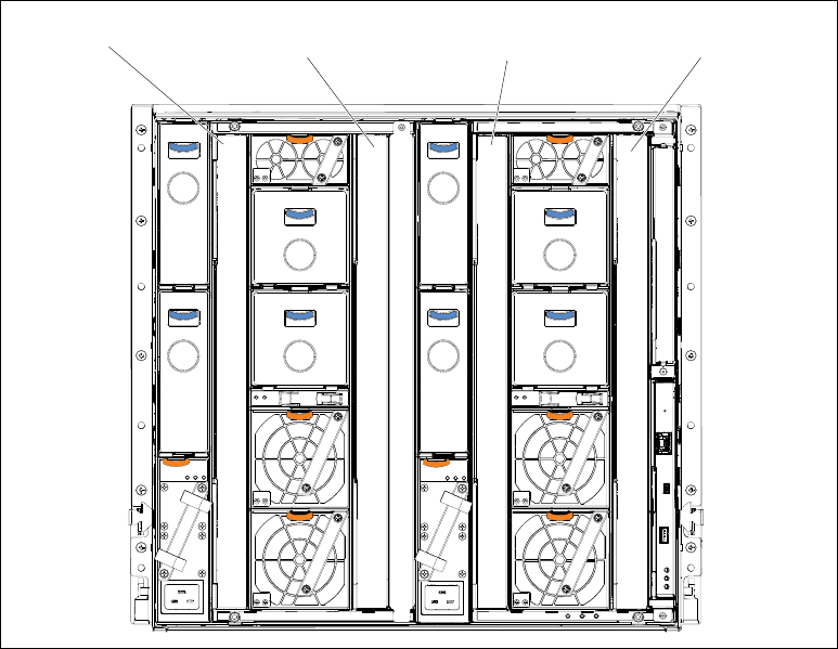
The Enterprise Chassis can accommodate four I/O modules installed in vertical orientation
into the rear of the chassis, as shown in Figure 4-32.
Figure 4-32 Rear view that shows the I/O Module bays 1-4
If a node has a two port integrated LAN on Motherboard (LOM) as standard, Module 1 and 2
are connected to this LOM. If an I/O adapter is installed in the nodes I/O expansion bay 1,
Modules 1 and 2 would be connected to this LOM.
Modules 3 and 4 connect to the I/O adapter that is installed within I/O expansion bay 2 on the
node.
These I/O modules provide external connectivity, and connect internally to each of the nodes
within the chassis. They can be either Switch or Pass thru modules, with a potential to
support other types in the future.
I/O module
bay 1
I/O module
bay 3
I/O module
bay 2
I/O module
bay 4
86 IBM PureFlex System and IBM Flex System Products and Technology
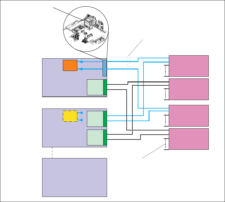
Figure 4-33 shows the connections from the nodes to the switch modules.
Figure 4-33 LOM, I/O adapter, and switch module connections
The node in Bay 1 on Figure 4-33 shows that when shipped with a LOM, the LOM connector
provides the link from the node system board to the midplane. Some nodes do not ship with
LOM.
If required, this LOM connector can be removed and an I/O expansion adapter installed in its
place. This configuration is shown on the node in Bay 2 on Figure 4-33
Node
bay 1
with LOM
Node
bay 2
with I/O
expansion
adapter
Node
bay 14
LOM
LOM connector
(remove when
I/O expansion
adapter is installed)
I/O module 1
I/O module 3
I/O module 2
I/O module 4
LOM
4 lanes (KX-4) or
4 10 Gbps lanes (KR)
14 internal groups
(of 4 lanes each),
one to each node.
87
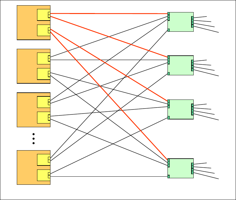
Figure 4-34 shows the electrical connections from the LOM and I/O adapters to the I/O
Modules, which all takes place across the chassis midplane.
Figure 4-34 Logical layout of node to switch interconnects
A total of two I/O expansion adapters (designated M1 and M2 in Figure 4-34) can be plugged
into a half-wide node. Up to 4 I/O adapters can be plugged into a full-wide node.
Each I/O adapter has two connectors. One connects to the compute node’s system board
(PCI Express connection). The second connector is a high speed interface to the midplane
that mates to the midplane when the node is installed into a bay within the chassis.
As shown in Figure 4-34, each of the links to the midplane from the I/O adapter (shown in red)
are in fact four links wide. Exactly how many links are employed on each I/O adapter is
dependent on the design of the adapter and the number of ports that are wired. Therefore, a
half wide node can have a maximum of 16 I/O links, and a full wide node 32.
Node
14
M1
M2
Node
3
M1
M2
Node
2
M1
M2
Node
1
M1
M2
Switch
1
Switch
2
Switch
3
Switch
4
.
.
.
.
.
.
.
.
.
.
.
.
Each line between an I/O adapter and a switch is four links
88 IBM PureFlex System and IBM Flex System Products and Technology
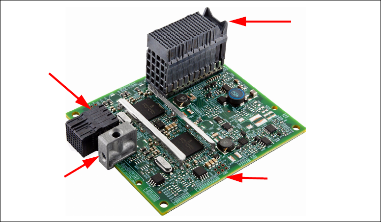
Figure 4-35 shows an I/O expansion adapter.
Figure 4-35 I/O expansion adapter
Each of these individual I/O links or lanes can be wired for 1 Gb or 10 Gb Ethernet, or 8 or 16
Gbps Fibre Channel. You can enable any number of these links. The application-specific
integrated circuit (ASIC) type on the I/O Expansion adapter dictates the number of links that
can be enabled. Some ASICs are two port and some are four port. For a two port ASIC, one
port can go to one switch and one port to the other. This configuration is shown in Figure 4-36
on page 89. In the future other combinations can be implemented.
In an Ethernet I/O adapter, the wiring of the links is to the IEEE 802.3ap standard, which is
also known as the
Backplane Ethernet standard. The Backplane Ethernet standard has
different implementations at 10 Gbps, being 10GBASE-KX4 and 10GBASE-KR. The I/O
architecture of the Enterprise Chassis supports both the KX4 and KR.
10GBASE-KX4 uses the same physical layer coding (IEEE 802.3 clause 48) as
10GBASE-CX4, where each individual lane (SERDES = Serializer/DeSerializer) carries
3.125 Gbaud of signaling bandwidth.
10GBASE-KR uses the same coding (IEEE 802.3 clause 49) as 10GBASE-LR/ER/SR, where
the SERDES lane operates at 10.3125 Gbps.
Each of the links between I/O expansion adapter and I/O module can either be 4x 3.125
Lanes/port (KX-4) or 4x 10 Gbps Lanes (KR). This choice is dependent on the expansion
adapter and I/O Module implementation.
PCIe
connector
Guide block to
ensure correct
installation
Midplane
connector
Adapters share a
common size
(100 mm x 80 mm)
Get IBM PureFlex System and IBM Flex System Products and Technology now with the O’Reilly learning platform.
O’Reilly members experience books, live events, courses curated by job role, and more from O’Reilly and nearly 200 top publishers.

