223
To optimize software licensing, you can unconfigure or disable one or more cores. The feature
is listed in Table 5-56.
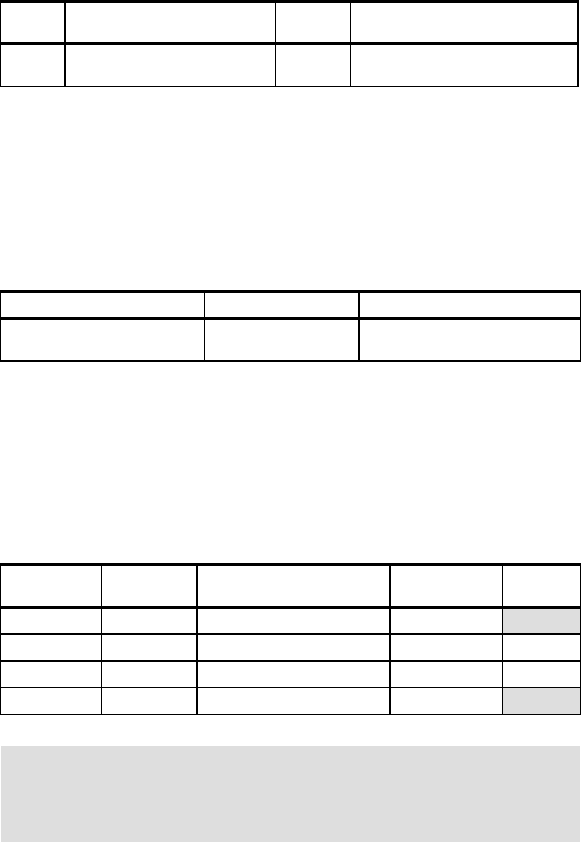
Table 5-56 Unconfiguration of cores
5.5.7 Memory
Each POWER7 processor has two integrated memory controllers in the chip. Industry
standard DDR3 RDIMM technology is used to increase reliability, speed, and density of
memory subsystems.
Memory placement rules
The preferred memory minimum and maximums for the p460 are shown in Table 5-57.
Table 5-57 Preferred memory limits for the p460
Use a minimum of 2 GB of RAM per core. The functional minimum memory configuration for
the system is 4 GB (2x2 GB) but that is not sufficient for reasonable production use of the
system.
LP and VLP form factors
One benefit of deploying IBM Flex System systems is the ability to use LP memory DIMMs.
This design allows for more choices to configure the system to match your needs.
Table 5-58 lists the available memory options for the p460.
Table 5-58 Memory options for the p460
Feature
code
Description Minimum Maximum
2319 Factory Deconfiguration of 1-core 0 1 less than the total number of cores
(For EPR5, the maximum is 7)
Model Minimum memory Maximum memory
IBM Flex System p460 Compute
Node
32 GB 512 GB (32x 16 GB DIMMs)
Part
number
Feature
code
Description Speed Form
factor
78P1011 EM04 2 GB DDR3 DIMM 1066 MHz
LP
78P0501 8196 4 GB DDR3 DIMM 1066 MHz VLP
78P0502 8199 8 GB DDR3 DIMM 1066 MHz VLP
78P0639 8145 16 GB DDR3 DIMM 1066 MHz
LP
Requirement: Due to the design of the on-cover storage connections, if you use SAS
HDDs, you
must use VLP DIMMs (4 GB or 8 GB). The cover cannot close properly if VLP
DIMMs and SAS hard disk drives are configured in the same system. Combining the two
physically obstructs the cover from closing. For more information, see 5.4.10, “Storage” on
page 209.
224 IBM PureFlex System and IBM Flex System Products and Technology
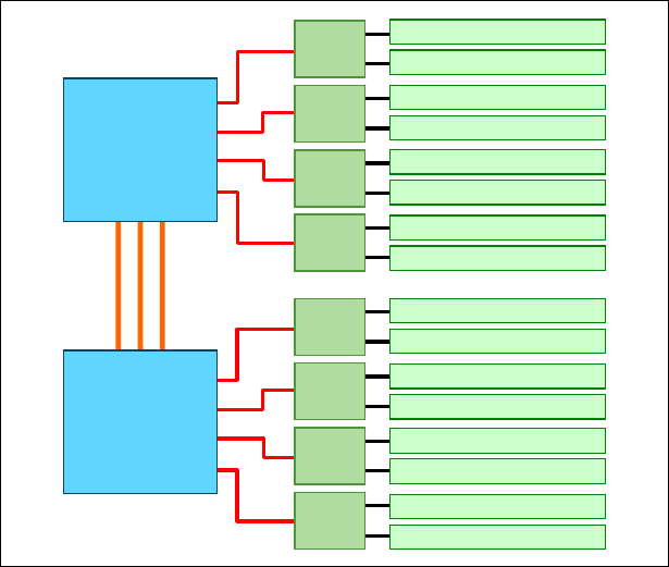
There are 16 buffered DIMM slots on the p260 and the p24L, as shown in Figure 5-52. The
IBM Flex System p460 Compute Node adds two more processors and 16 additional DIMM
slots, divided evenly (eight memory slots) per processor.
Figure 5-52 Memory DIMM topology (Processors 0 and 1 shown)
The memory-placement rules are as follows:
Install DIMM fillers in unused DIMM slots to ensure efficient cooling.
Install DIMMs in pairs. Both need to be the same size.
Both DIMMs in a pair must be the same size, speed, type, and technology. You can mix
compatible DIMMs from multiple manufacturers.
Install only supported DIMMs, as described on the IBM ServerProven website:
http://www.ibm.com/servers/eserver/serverproven/compat/us/
SMI
SMI
SMI
SMI
SMI
SMI
SMI
SMI
POWER7
Processor 1
POWER7
Processor 0
DIMM 1 (P1-C1)
DIMM 2 (P1-C2)
DIMM 3 (P1-C3)
DIMM 4 (P1-C4)
DIMM 5 (P1-C5)
DIMM 6 (P1-C6)
DIMM 7 (P1-C7)
DIMM 8 (P1-C8)
DIMM 9 (P1-C9)
DIMM 10 (P1-C10)
DIMM 11 (P1-C11)
DIMM 12 (P1-C12)
DIMM 13 (P1-C13)
DIMM 14 (P1-C14)
DIMM 15 (P1-C15)
DIMM 16 (P1-C16)
Get IBM PureFlex System and IBM Flex System Products and Technology now with the O’Reilly learning platform.
O’Reilly members experience books, live events, courses curated by job role, and more from O’Reilly and nearly 200 top publishers.

