194 IBM PureFlex System and IBM Flex System Products and Technology
devices are listed in the boot menu. This configuration allows you to boot from either device,
or set one as a backup in case the first gets corrupted.
The supported USB memory keys are listed in Table 5-41.
Table 5-41 Virtualization options
5.3.12 Systems management
The following section describes some of the systems management features that are available
with the x220.
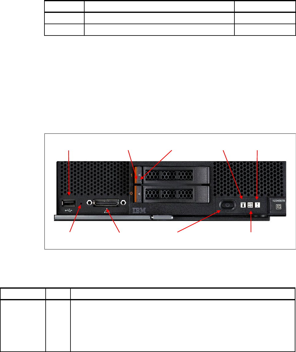
Front panel LEDs and controls
The front of the x220 includes several LEDs and controls that assist in systems management.
They include a hard disk drive activity LED, status LEDs, and power, identify, check log, fault,
and light path diagnostic LEDs. Figure 5-32 shows the location of the LEDs and controls on
the front of the x220.
Figure 5-32 The front of the x220 with the front panel LEDs and controls shown
Table 5-42 describes the front panel LEDs.
Table 5-42 x220 front panel LED information
Part number Description Maximum supported
41Y8300 IBM USB Memory Key for VMware ESXi 5.0 2
41Y8298 IBM Blank USB Memory Key for VMware ESXi Downloads 2
USB port
Console Breakout
Cable port
Power button / LED
Hard disk drive
activity LED
Hard disk drive
status LED Identify LED
Check log LED
Fault LED
NMI control
LED Color Description
Power Green This LED lights solid when system is powered up. When the compute node is initially
plugged into a chassis, this LED is off. If the power-on button is pressed, the IMM flashes
this LED until it determines that the compute node is able to power up. If the compute node
is able to power up, the IMM powers the compute node on and turns on this LED solid. If
the compute node is not able to power up, the IMM turns off this LED and turns on the
information LED. When this button is pressed with the server out of the chassis, the light
path LEDs are lit.

195
Table 5-43 describes the x220 front panel controls.
Table 5-43 x220 front panel control information
Power LED
The status of the power LED of the x220 shows the power status of the compute node. It also
indicates the discovery status of the node by the Chassis Management Module. The power
LED states are listed in Table 5-44.
Table 5-44 The power LED states of the x240 compute node
Location Blue A user can use this LED to locate the compute node in the chassis by requesting it to flash
from the chassis management module console. The IMM flashes this LED when instructed
to by the Chassis Management Module. This LED functions only when the server is
powered on.
Check error log Yellow The IMM turns on this LED when a condition occurs that prompts the user to check the
system error log in the Chassis Management Module.
Fault Yellow This LED lights solid when a fault is detected somewhere on the compute node. If this
indicator is on, the general fault indicator on the chassis front panel should also be on.
Hard disk drive
activity LED
Green Each hot-swap hard disk drive has an activity LED, and when this LED is flashing, it
indicates that the drive is in use.
Hard disk drive
status LED
Yellow When this LED is lit, it indicates that the drive has failed. If an optional IBM ServeRAID
controller is installed in the server, when this LED is flashing slowly (one flash per second),
it indicates that the drive is being rebuilt. When the LED is flashing rapidly (three flashes
per second), it indicates that the controller is identifying the drive.
LED Color Description
Control Characteristic Description
Power on / off
button
Recessed with Power
LED
If the server is off, pressing this button causes the server to power up and
start loading. When the server is on, pressing this button causes a graceful
shutdown of the individual server so it is safe to remove. This process
includes shutting down the operating system (if possible) and removing
power from the server. If an operating system is running, the button might
have to be held for approximately 4 seconds to initiate the shutdown. This
button must be protected from accidental activation. Group it with the Power
LED.
NMI Recessed. It can be
accessed only by using
a small pointed object.
Causes an NMI for debugging purposes.
Power LED state Status of compute node
Off No power to compute node
On; fast flash mode Compute node has power
Chassis Management Module is in discovery mode (handshake)
On; slow flash mode Compute node has power
Power in stand-by mode
On; solid Compute node has power
Compute node is operational
Exception: The power button does not operate when the power LED is in fast flash mode.
Get IBM PureFlex System and IBM Flex System Products and Technology now with the O’Reilly learning platform.
O’Reilly members experience books, live events, courses curated by job role, and more from O’Reilly and nearly 200 top publishers.

