236 IBM eX5 Implementation Guide
6.5.2 Processor requirements
To maximize performance, both nodes must have all four processors and all memory cards
installed and populated. However, the x3850 X5 does support 2-node configurations with only
two processors installed in each node.
The following list shows the processor requirements to perform scaling:
Functioning processors must exist in processor sockets 1 and 4 of both servers.
The processor specification must match among all processors in both servers.
6.5.3 Memory requirements
For scaling to be permitted, you must install the memory in such a way so as to support
Hemisphere Mode on the processors of both nodes. See Table 3-15 on page 81 to see which
memory configurations enable Hemisphere Mode.
To maximize performance, all four processors in both nodes must be in Hemisphere Mode. If
needed, the servers can be scaled with only processors 1 and 4 in Hemisphere Mode in both
nodes, but this type of configuration cannot support operating systems, such as VMware. For
other less sensitive operating environments, if the unlikely failure of a memory card takes
processor 1 or 4 out of Hemisphere Mode, you can restore the scaled environment by
swapping memory cards from processor 2 or 3.
6.5.4 Cabling the servers together
The QPI cables that are used to cable the two x3850 X5s together are extremely short and
stiff. To plug the cables in, you must start the cable insertion on both sides of the cable into
the correct receptors on both x3850 X5s at the same time.
Use the following tips when plugging in the cables:
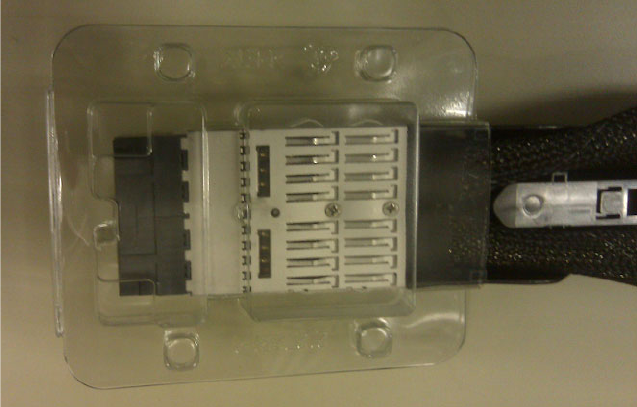
QPI cables ship packaged with reusable plastic boots that protect the fragile outside
edges of the cable connectors, as shown in Figure 6-12. It is a good idea to keep a set of
these plastic boots if you want to remove the QPI cables for the movement of equipment
from rack to rack or for servicing the unit.
Figure 6-12 Reusable QPI cable connector protective boot
Chapter 6. IBM System x3850 X5 and x3950 X5 237
There are four QPI cables connecting all of the QPI ports of both x3850 X5 servers.
Figure 6-13 shows the cable routing.
Figure 6-13 Cabling diagram for 2-node x3850 X5
Consider this important information:
The QPI cables are keyed to be inserted only one way. A quick visual check for cable
orientation is to look for the blue retainer release tab on the top of each cable end. The
blue retainer release tab is placed on what becomes the visible top of the cable when the
cable is installed correctly.
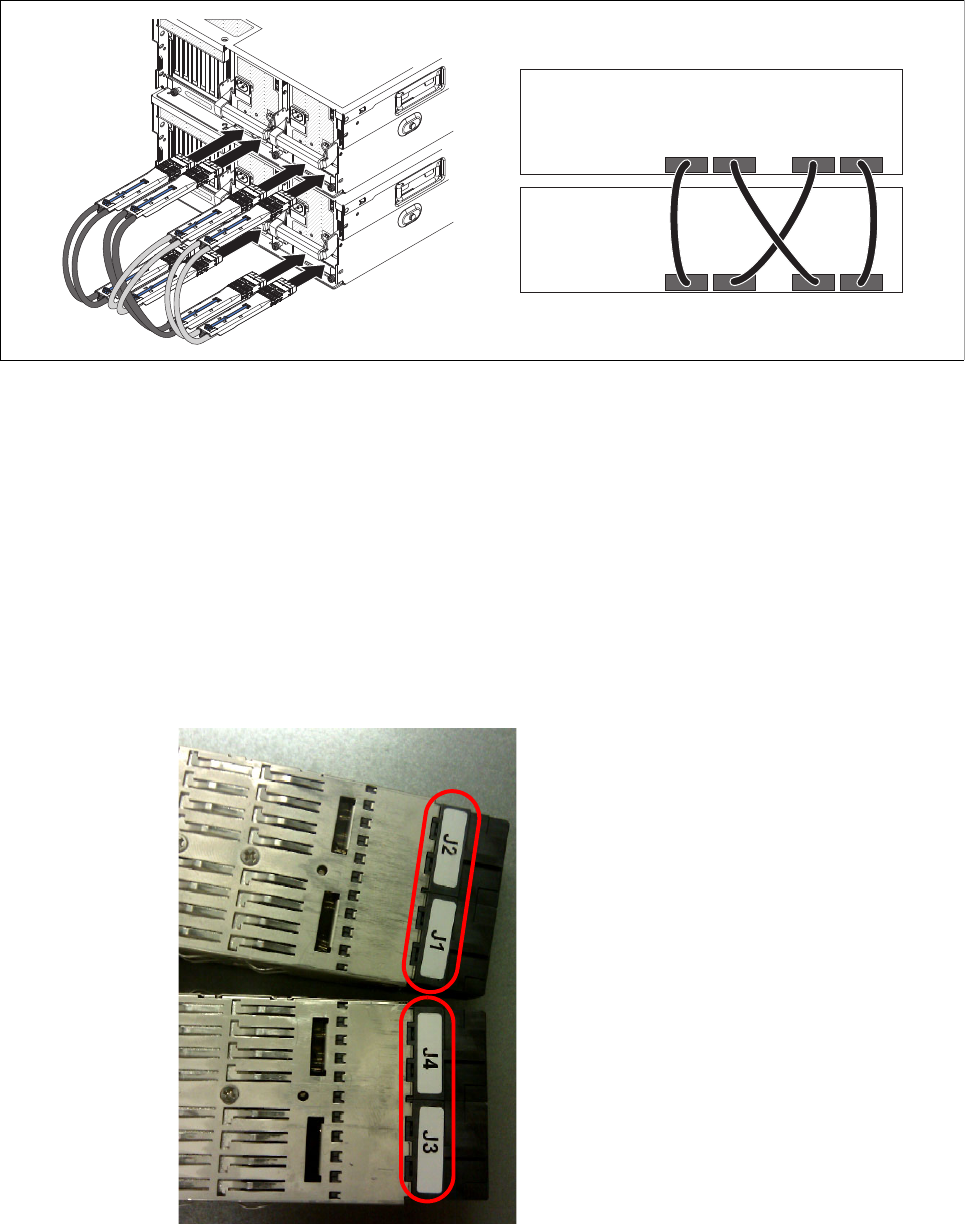
The ends of the cable are labeled to indicate which end can be inserted into the correct
equipment. The server that becomes the primary node has the end of the QPI plugged
into it with the labels J2 and J1, as shown in Figure 6-14. The secondary node has the end
of the QPI cable plugged into it with the labels J4 and J3. All four QPI cables must be
oriented in the exact same manner. Neither server can power on if the cables are not
consistent in their orientation. Figure 6-14 shows how the cable ends are labeled.
Figure 6-14 QPI cable end labels: J1 and J2 attach to the primary node
Rack rear
Get IBM eX5 Implementation Guide now with the O’Reilly learning platform.
O’Reilly members experience books, live events, courses curated by job role, and more from O’Reilly and nearly 200 top publishers.

