196 IBM eX5 Implementation Guide
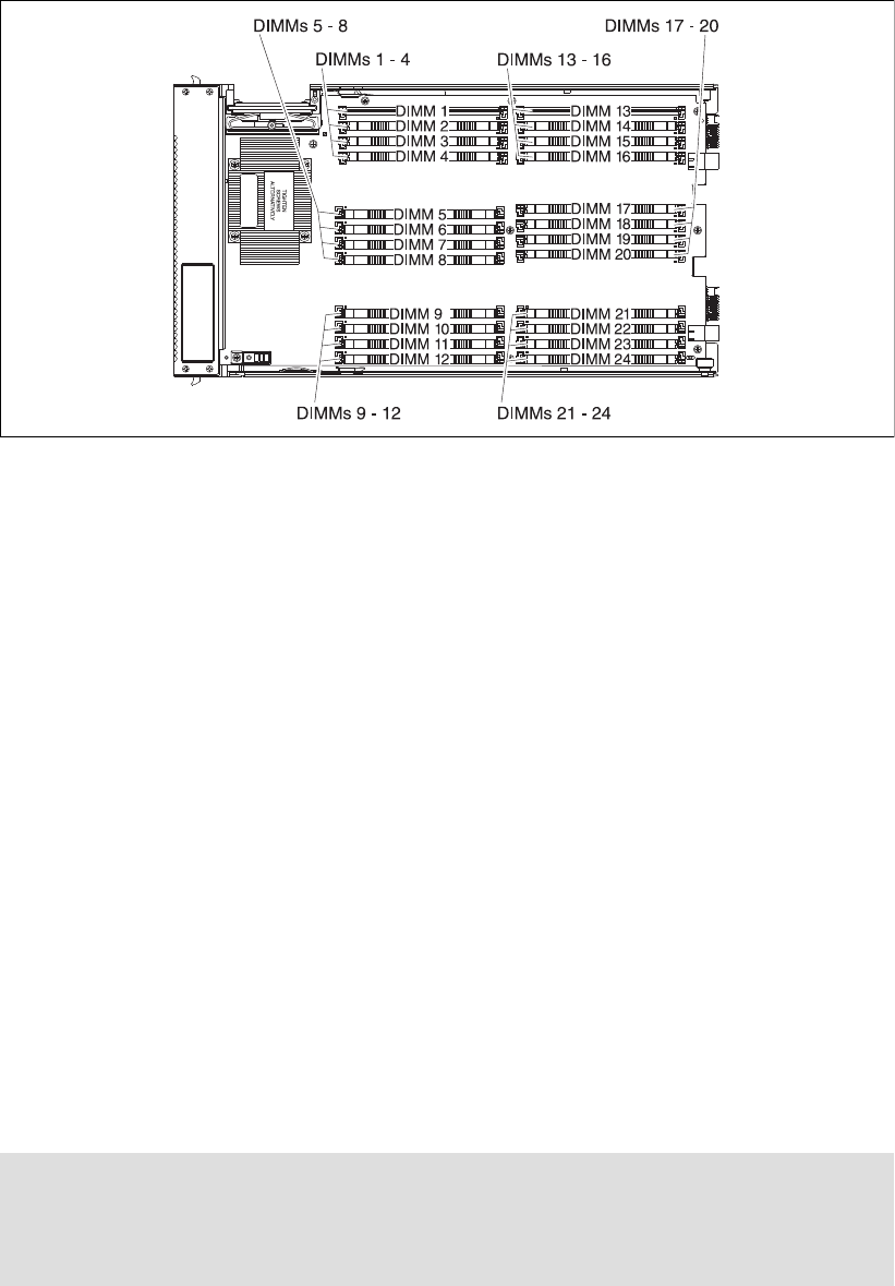
Figure 5-14 DIMM layout on the MAX5 system board
MAX5 memory runs at 1066, 978, or 800 MHz DDR3 speeds. The memory speed is
dependent on the processor QPI speed in the HX5:
A QPI speed of 6.4 GHz means the speed of the MAX5 memory is 1066 MHz.
A QPI speed of 5.8 GHz means the speed of the MAX5 memory is 978 MHz.
A QPI speed of 4.8 GHz means the speed of the MAX5 memory is 800 MHz.
Table 5-12 on page 192 indicates these memory speeds for each processor.
To see more information about how memory speed is calculated with QPI, see 2.3.1,
“Memory speed” on page 22.
5.10.2 DIMM population order
Installing DIMMs in the HX5 and MAX5 in the correct order is essential for system
performance. See 5.10.4, “Memory mirroring” on page 200 for the effects on performance
when you do not install the DIMMs in the correct order.
HX5 memory population order
As shown in Figure 5-12 on page 195, the HX5 design has two DIMMs per memory buffer
and one DIMM socket per memory channel.
For best performance, install the DIMMs in the sockets, as shown in Table 5-14 on page 197.
This sequence spreads the DIMMs across as many memory buffers as possible.
Installation methods: These configurations use the most optimized method for
performance. For optional installation methods, see the BladeCenter HX5 Problem
Determination and Service Guide at the following website:
http://ibm.com/support/entry/portal/docdisplay?lndocid=MIGR-5084529

Chapter 5. IBM BladeCenter HX5 197
Table 5-14 NUMA-compliant DIMM installation for a single-node HX5
In a 2-node (4-socket) configuration with two HX5 servers, follow the memory installation
sequence in both nodes. You must populate memory to have a balance for each processor in
the configuration.
For best performance, use the following general guidelines:
Install as many DIMMs as possible. You can get the best performance by installing DIMMs
in every socket.
Each processor needs to have identical amounts of RAM.
Spread out the memory DIMMs to all memory buffers. That is, install one DIMM to a
memory buffer before beginning to install a second DIMM to that same buffer. See
Table 5-14 for DIMM placement.
You must install memory DIMMs in the order of the DIMM size with largest DIMMs first,
then next largest DIMMs, and so on. Placement must follow the DIMM socket installation
that is shown in Table 5-14.
To maximize performance of the memory subsystem, select a processor with the highest
memory bus speed (as listed in Table 5-12 on page 192).
The lower value of the processor’s memory bus speed and the DIMM speed determine
how fast the memory bus can operate. Every memory bus operates at this speed.
Table 5-15 NUMA-compliant DIMM installation for a 2-node HX5
Number of CPUs
Number of DIMMs
Hemisphere Mode
a
a. For more information about Hemisphere Mode and its importance, see 2.3.5, “Hemisphere
Mode” on page 26.
Processor 1 Processor 2
Buffer Buffer Buffer Buffer Buffer Buffer Buffer Buffer
DIMM 1
DIMM 2
DIMM 3
DIMM 4
DIMM 5
DIMM 6
DIMM 7
DIMM 8
DIMM 9
DIMM 10
DIMM 11
DIMM 12
DIMM 13
DIMM 14
DIMM 15
DIMM 16
24Nx x x x
28
Y x x x x x x x x
212N
x x x x x x x x x x x x
216
Y x x x x x x x x x x x x x x x x
Number of CPUs
Number of DIMMs
Hemisphere Mode
a
Processor 1 Processor 2
Buffer Buffer Buffer Buffer Buffer Buffer Buffer Buffer
DIMM 1
DIMM 2
DIMM 3
DIMM 4
DIMM 5
DIMM 6
DIMM 7
DIMM 8
DIMM 9
DIMM 10
DIMM 11
DIMM 12
DIMM 13
DIMM 14
DIMM 15
DIMM 16
48Nx x x x
416
Y x x x x x x x x
424N
x x x x x x x x x x x x
432
Y x x x x x x x x x x x x x x x x
Get IBM eX5 Implementation Guide now with the O’Reilly learning platform.
O’Reilly members experience books, live events, courses curated by job role, and more from O’Reilly and nearly 200 top publishers.

