Chapter 4. Orchestrating Data Movement and Transformation
When you work in a data-driven role (e.g., as a bioinformatician, data scientist, data analyst, etc.), having data available to you is paramount to being successful. With a cloud environment, a common hurdle that organizations have when they first start out is actually getting data into the cloud for everyone to use. Data orchestration encompasses the processes for getting data into and out of cloud resources and also managing certain data tasks. In this chapter, we’ll learn how to orchestrate data movement in the cloud by connecting to sources (often outside our cloud environment) and copying data over to our data lake or other destination.
In Azure, the standard tool for data orchestration is called Data Factory. This tool blends the capabilities of a traditional extract-transform-load (ETL) tool, like SQL Server Integration Services, with orchestration capabilities for queuing up external data tasks. With Data Factory, we’ll learn how to extract data from outside our Azure environment into our data lake and also learn how to transform and load that data into our data warehouse. See Figure 4-1.
Outside of Azure, there are certainly other third-party ETL tools available for you to purchase, but it’s worth giving Data Factory a shot as it is very well-integrated with the other Azure services that we cover in this book. Plus, Data Factory supports more than 90 built-in connectors to common enterprise platforms like SAP, Snowflake, AWS S3 Buckets, and more. This allows you to start moving data into your Azure-based databases, data warehouses, and data lakes very quickly. In addition to other cloud sources, there are connectors for standard protocols like SFTP and HTTP, which makes pulling data from public -omics repositories straightforward. So, pulling large reference genomes or extra public samples to use in your research can now be performed in the cloud without you having to download and re-upload the data from your local workstation.
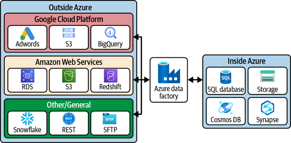
Figure 4-1. Some example connectors included in Data Factory
While there are bioinformatics pipeline tools like NextFlow and Snakemake that perform analytical tasks, this chapter will focus on data-centric tasks such as copying data up to the cloud, moving it around, and performing some basic data transformations in Data Factory.
Coming up, we’ll provision our Data Factory service and start building a pipeline to move data around.
Creating Your Data Factory
If you created a Synapse Analytics Workspace in Chapter 3, you can skip to the section “Getting Started with Data Movement,” as Synapse comes with a Data Factory instance already available from its UI. Otherwise, we can create a standalone Data Factory service in just a few steps from the Azure Portal. The Synapse-housed Data Factory and the standalone version work almost identically, so the choice is yours. I find the Synapse-housed version a little easier to start with as it comes preconfigured with the credentials to connect to the data that’s in the data warehouse. (In the standalone version, there’s just an extra step to set up this access.)
Navigate to the main page of the Azure Portal and click “+ Create a resource.” Search for “Data Factory,” which should automatically bring up the page to create the Data Factory resource. See Figure 4-2.
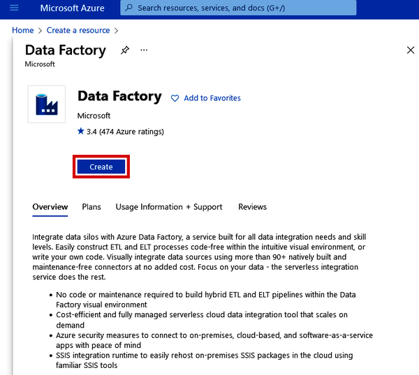
Figure 4-2. Creating an Azure Data Factory resource from the Azure Marketplace
Click the “Create” button. This will take you to a Create Data Factory form, which should look similar to the other setup processes we’ve gone through.
For Data Factory, there isn’t much to configure. Pick the resource group that you’ve been using (e.g., genomics-dev-rg), pick the region that houses all your other services, and then give your Data Factory a name (such as genomics-df). But wait: don’t click “Review + create” yet. We have to go to the “Git configuration” tab next, as shown in Figure 4-3.
Data Factory integrates well with Azure DevOps and GitHub Git repositories. When you write SQL scripts to create tables or query data, these can be automatically committed to your Git repository when you click the “Publish” button (which you’ll see in a bit). This is also helpful for saving any data pipelines that you create inside Data Factory. Since this configuration can be updated later, let’s click the checkbox beside “Configure Git later” (as shown in Figure 4-4) and just proceed without it for now.
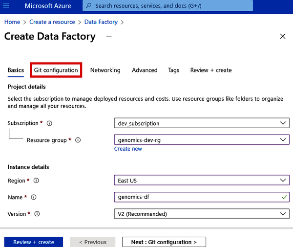
Figure 4-3. Basic settings for Azure Data Factory
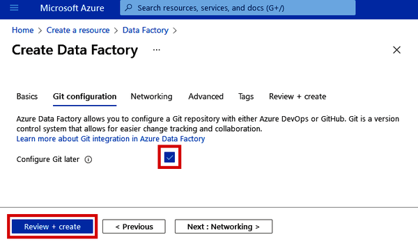
Figure 4-4. Git configuration during Azure Data Factory setup
Now you can click the “Review + create” button. Once Azure performs its validation check, you can then click “Create” (as shown in Figure 4-5), which will provision your Data Factory in just a few seconds.
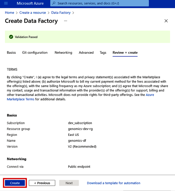
Figure 4-5. Git configuration during Azure Data Factory setup
Now that we have Data Factory up and running, let’s create our first data orchestration task by copying data into our cloud environment.
Getting Started with Data Movement
In the following sections, we’ll be walking through how data orchestration works within Data Factory to copy data, move it around, and even transform it. We’ll also be able to tell other services when to perform actions on our data.
Getting Data into Your Data Lake Using the Copy Data Tool
The first step to doing anything in the cloud is moving some data up to Azure. One option is to take the manual route, which is to download data to your local computer and then upload it to our data lake. This may be fine for a small number of tiny files, but what happens if we have a lot of data we want to copy over?
Downloading and uploading gigabytes (or even terabytes) of data manually is a slow and futile exercise. Azure Data Factory has the Copy Data tool, which I find really useful for this exact task.
From the standalone Data Factory, you can use the Copy Data tool right from the main screen. Click the “Ingest” button, as shown in Figure 4-6.
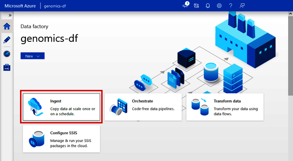
Figure 4-6. Locating the Copy Data tool from Azure Data Factory
If you’re using Synapse, you’ll find the Copy Data tool under the “Integrate” tab. As shown in Figure 4-7, click the “+” at the top and select “Copy Data tool.”
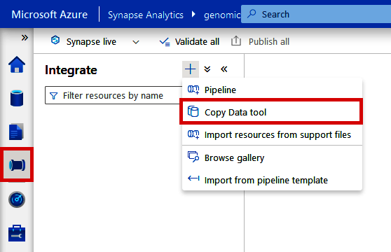
Figure 4-7. Locating the Copy Data tool from Azure Synapse Analytics
The next screen is the same whether you’re using the standalone version of Data Factory or the version built into Synapse. Click “Built-in copy task” and then click the “Next” button. See Figure 4-8.
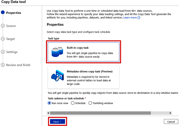
Figure 4-8. Selecting the Built-in copy task in the Copy Data tool
Linking to NCBI’s FTP Server
In research, we often rely on public data repositories to provide reference genomes, public sequences and samples, additional metadata or ancillary information, and more. Thus, it’s useful to have the ability to pull this data into our Azure environment in an automated and scalable way.
Many public data repositories like National Center for Biotechnology Information (NCBI) provide access to their data through FTP (file transfer protocol). In Data Factory, we can directly connect to FTP sites and copy data right from Data Factory to our Data Lake. In this example, we’ll grab a sample VCF file from NCBI’s FTP server and copy it to our data lake, which we’ll use later.
On the next step of the Copy Data tool (“2. Source”), set the “Source type” to “FTP” (note how many other options there are in this drop-down list) and click “+ New connection” beside the “Connection” drop-down. See Figure 4-9.
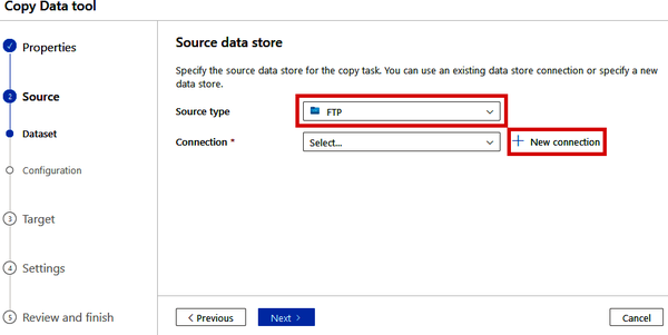
Figure 4-9. Specifying an FTP source in the Copy Data tool
In the “New connection” blade that pops up, give this connection a name (such as “NCBI_FTP”). In the “Host” box, paste in the following URL:
ftp://ftp.ncbi.nlm.nih.gov
As shown in Figure 4-10, disable SSL under “Secure Transmission” and set the “Authentication type” to “Anonymous.” (Since this is a public site, we don’t have to log in.)
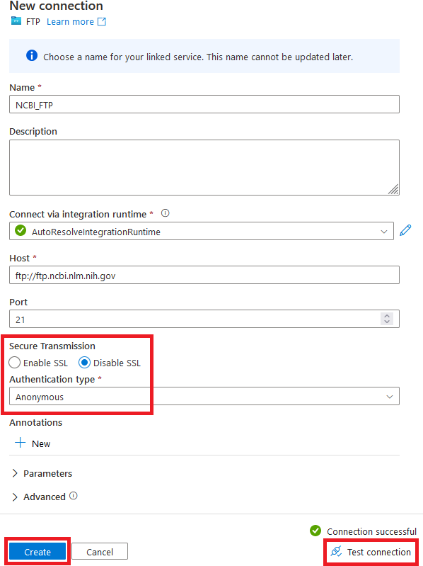
Figure 4-10. Configuring an FTP source to the NCBI FTP server
Once you have these properties filled out, click the “Test connection” button at the bottom of the screen. If you get a green check mark, click the “Create” button to create the connection to the NCBI FTP server.
On the next screen, we’ll provide the information about the specific file that we want to copy. In the “File or folder” box, you can click the “Browse” button to explore the FTP site and find the file(s) that you’re wanting to copy. For now, simply copy the following path into the box:
toolbox/gbench/samples/vcf/GCA_000001215.4_current_ids.vcf.gz
Since this is a compressed VCF file (about 60MB), we can use the binary copy option to avoid having Data Factory check the schema of the file being copied. See Figure 4-11 for the other recommended selections for the “Options” section.
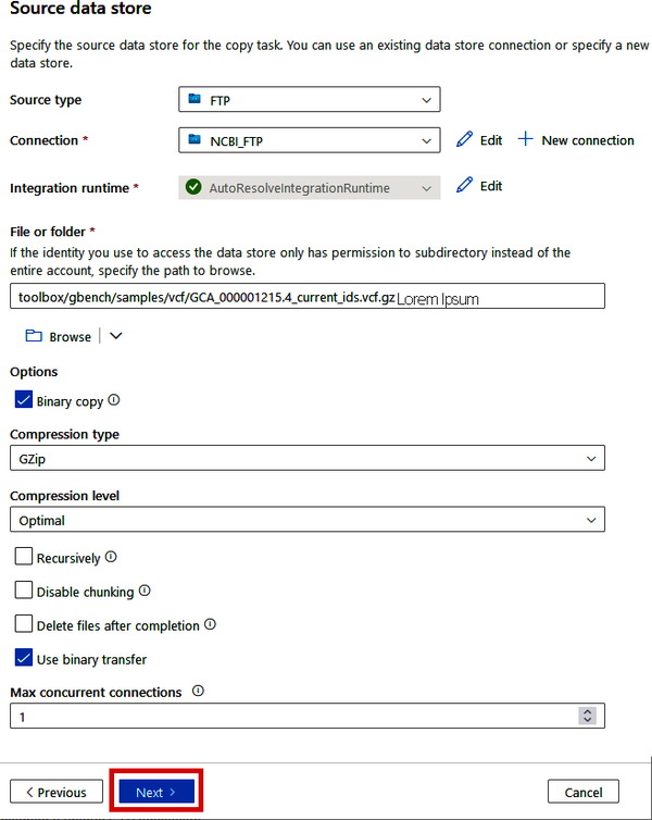
Figure 4-11. Configuring the FTP source to a specific compressed VCF file
Once you’ve filled in this information, click the “Next >” button.
On the “Destination data store” screen (“3. Target”), you’ll now specify the location where this VCF file should be copied. We’ll be copying this file to our data lake that we created in Chapter 2, so select “Azure Data Lake Storage Gen2” for the “Target type.” If you’re using the Copy Data tool from Synapse, you’ll find your data lake in the “Connection” drop-down (from where we specified this connection during Synapse’s setup process). If you’re using the Copy Data tool in the standalone version of Data Factory, we haven’t yet made this connection, so you’ll need to click “+ New Connection,” as shown in Figure 4-12.

Figure 4-12. Selecting your data lake connection in the Copy Data tool
Note
Skip this step if you’re using Synapse or if you already see your data lake in the “Connection” drop-down.
Linking up your data lake with Data Factory is simple since both resources exist in the same Azure tenant. Simply give your connection a name (such as “GenomicsDataLake”) and then find your data lake under the “Storage account name” drop-down menu (after selecting the right subscription), as shown in Figure 4-13.
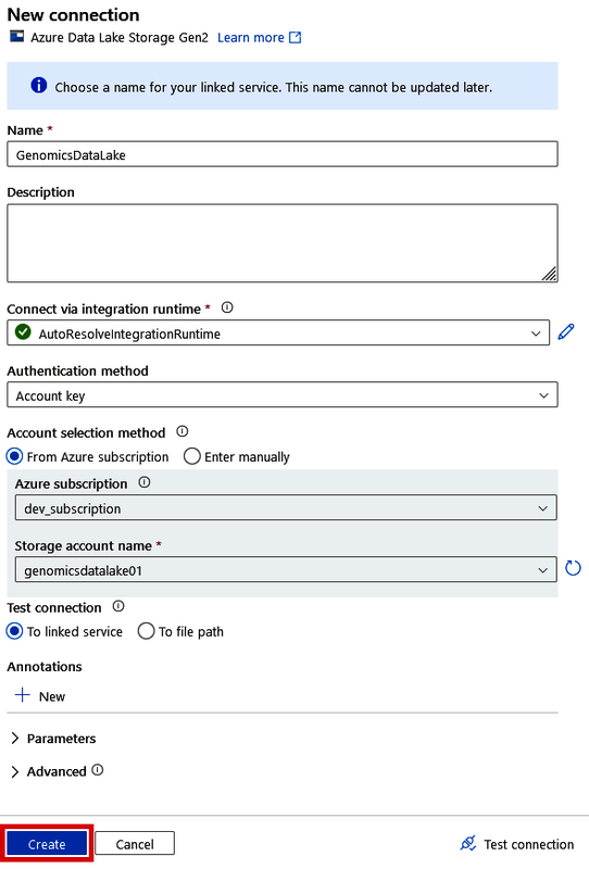
Figure 4-13. Creating a connection to your data lake in the Copy Data tool
This will automatically load the access keys for you so that you don’t have to go find them in the data lake. Click “Create” once it finds your genomics data lake.
Once you have your data lake selected in the Connection drop-down, proceed to fill out the remaining boxes in the “Destination data store” blade. For the “Folder path,” we can provide a path to a directory that doesn’t yet exist (such as “data/ncbidata”), and Data Factory will create it during the copying process. See Figure 4-14 for the rest of the recommended options. Once you’ve filled everything out, click the “Next” button.
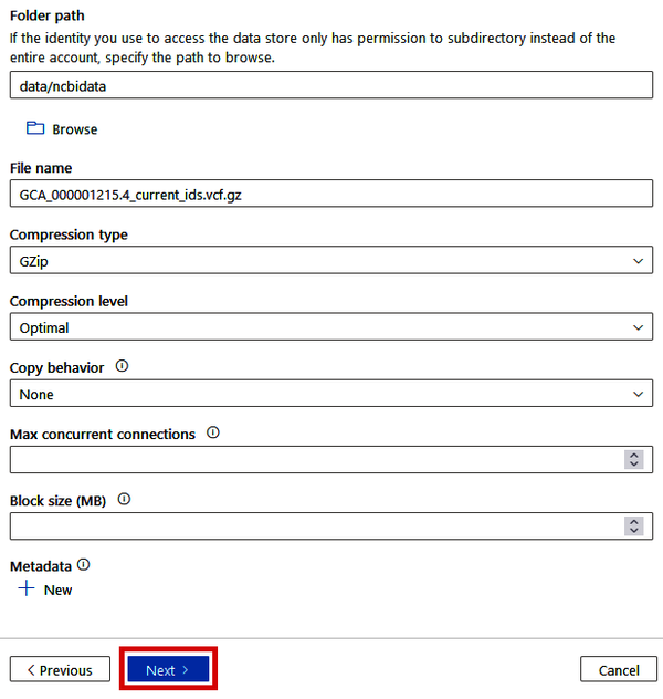
Figure 4-14. Specifying the data lake destination in the Copy Data tool
Then, on the “4. Settings” step, give your pipeline a name (such as “CopyNCBIVCFPipeline”) and click the “Next” button, as shown in Figure 4-15.
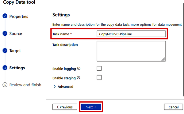
Figure 4-15. Naming the Copy Data pipeline
On the final “5. Review and finish” step, the Summary page will give you some information about the Copy Data pipeline that is to be executed. See Figure 4-16.
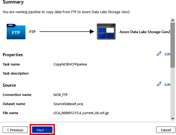
Figure 4-16. Reviewing the Copy Data pipeline settings
After reviewing the information, you can click the “Next” button. This will immediately kick off the pipeline and start copying this file from NCBI’s FTP server to your data lake. Once you see the green check marks, which indicate that the steps have succeeded, your VCF file is now in your data lake. See Figure 4-17.
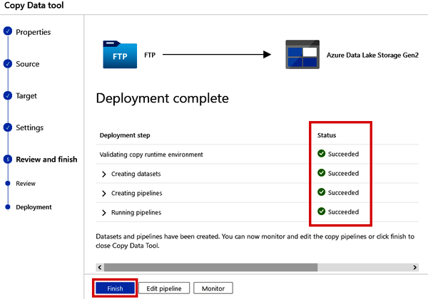
Figure 4-17. Completing the deployment of the Copy Data pipeline
Click the “Finish” button, as shown in Figure 4-17. Now you can navigate to your data lake to see if the VCF file is there.
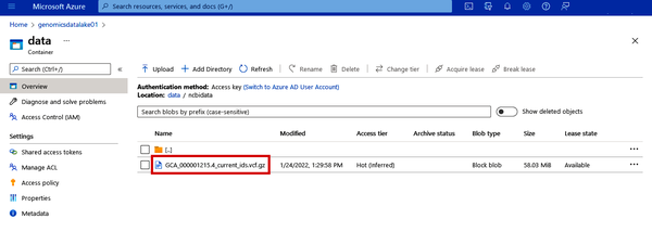
Figure 4-18. Validation that the VCF data has landed in your data lake
Now your data lake is no longer empty! See Figure 4-18. Repeat this process if you have more files in other systems that you want to copy over. In the next example, we’ll walk through the creation of more complex pipelines to actually transform data.
Transforming Data Using Data Flows
Sometimes, we may want to make some basic transformations on our data before loading it into our destination system. We can do this in Data Factory with Data Flows. While pipelines can move or copy data from place to place, we can use a Data Flow as a step in a pipeline to perform more complex transformations.
Parsing a VCF file with a data flow
Since we now have a VCF file in our data lake, let’s parse it using a Data Flow and then convert it to a more universally friendly format for cloud services like Synapse or Databricks.
If you’re using the Data Factory included in Synapse, navigate to the “Integrate” tab and click the + button at the top. Then, click “Pipeline.” See Figure 4-19.
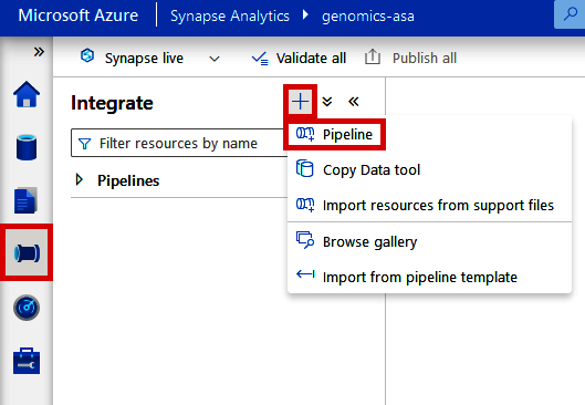
Figure 4-19. Creating a new pipeline from Azure Synapse Analytics Workspace
If you’re using a standalone version of Data Factory, navigate to the Author tab (pencil icon) and click the + button at the top. Then click “Pipeline” and “Pipeline.” See Figure 4-20.
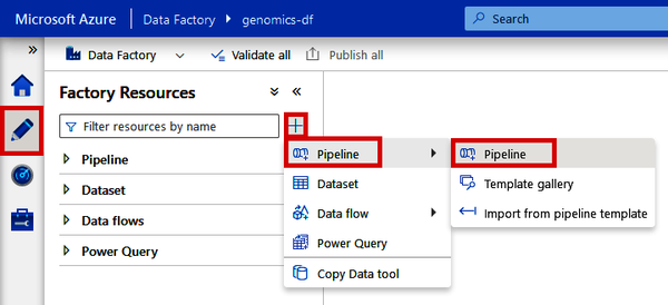
Figure 4-20. Creating a new pipeline from Azure Data Factory
This will open a new Pipeline canvas, where we can use the drag-and-drop interface to build out the steps of our pipeline. Under “Move & transform,” locate the “Data flow” module and drag it onto the canvas. Then click the “Data flow” module that is now on your canvas and locate the “Settings” tab at the bottom of the screen. Click the “+ New” button beside the “Data flow” drop-down menu, as shown in Figure 4-21.
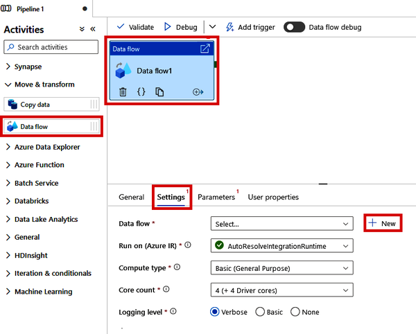
Figure 4-21. Creating a new Data Flow from a Data Factory pipeline
This will open a new canvas tab for the Data Flow, where we can define our data source, the transformation steps, and the “sink” or the destination where we want the transformed data to land.
To start building the Data Flow, click the “Add Source” box (shown in Figure 4-22). This will create a generic source step in the flow.
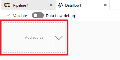
Figure 4-22. Adding a new source in a Data Factory Data Flow
Rename the “Output stream name” to “VCFSource” and click the “+ New” button next to the Dataset drop-down menu. See Figure 4-23.
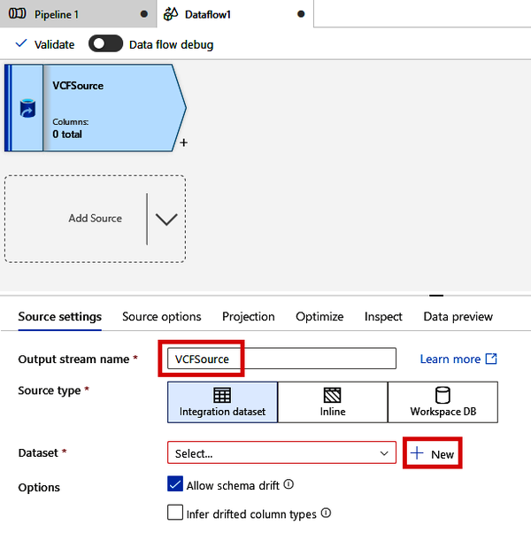
Figure 4-23. Creating a new source dataset for a Data Flow
In the “New integration dataset” windows that pop up, as shown in Figure 4-24, click “Azure Data Lake Storage Gen2” and click the “Continue” button.
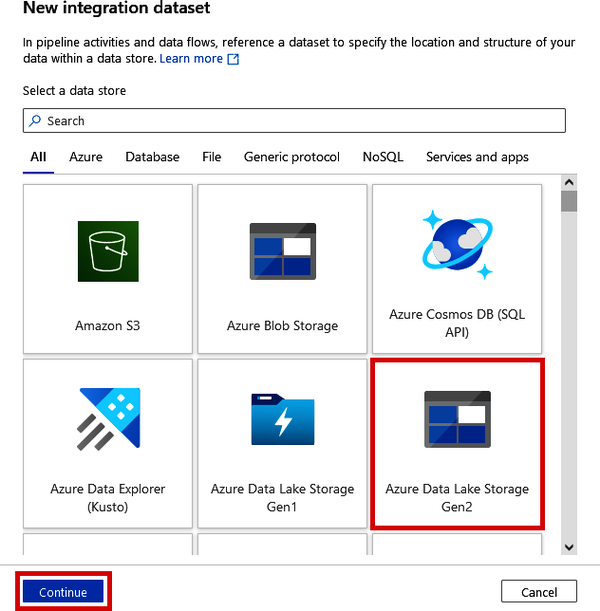
Figure 4-24. Connecting to an Azure Data Lake as an integration dataset
Next, specify that the type of file we want to interact with is a “DelimitedText” format and click the “Continue” button. (There isn’t a VCF format type in Data Factory, so we’ll need to make do with the more general delimited text format.) See Figure 4-25.
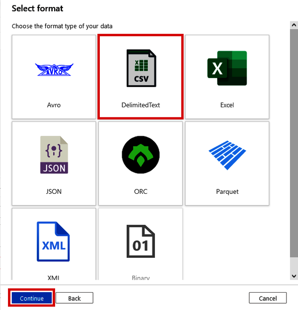
Figure 4-25. Selecting the DelimitedText format for an integration dataset
On the “Set properties” screen, shown in Figure 4-26, name this dataset “NCBIVCFFile” (or whatever you like) and select your data lake from the “Linked service” drop-down menu. This linked service will be either the “GenomicsDataLake” that we set up in Figure 4-13 (if you’re using a standalone Data Factory) or the workspace default storage “genomics-asa-WorkspaceDefaultStorage” (if you’re using a Data Factory in Synapse).
Also, specify the file path either by typing in the path to your VCF file in the format <container>/<folder>/<filename> or by clicking the folder button to browse the data lake and selecting the file. Lastly, click the “OK” button.
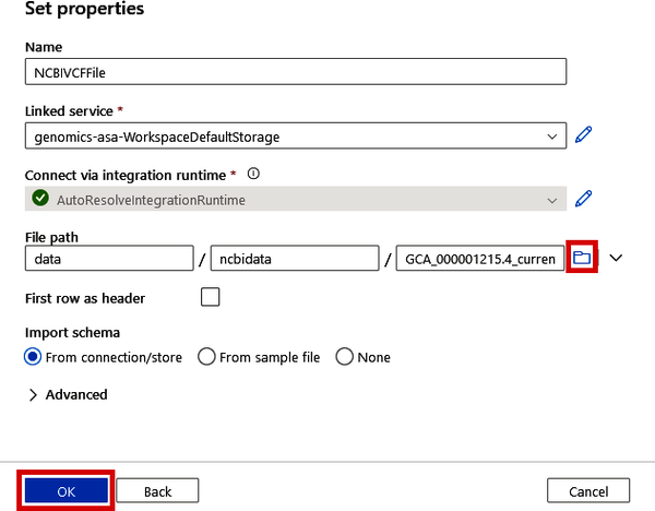
Figure 4-26. Specifying the path to a data lake file for an integration dataset
This will create the link to the VCF file. Now we need to check to see if Data Factory can actually read the file.
Back on the main Data Flow canvas, shown in Figure 4-27, turn on the “Data flow debug” toggle and click the “OK” button on the “Turn on data flow debug” window. This will give us a temporary compute context where we can test our Data Flow. While that’s spinning up, we need to specify a few things about our VCF file parsing.
Change the “Skip line count” to 17 (this is determined by looking at the VCF file to see how many ## header lines there are). Next, click the “Open” button beside “Dataset.”
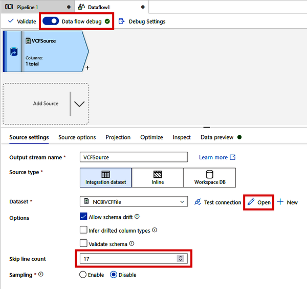
Figure 4-27. Turning on debug mode and specifying file-parsing settings
This will open a new canvas tab to allow you to further configure the connection settings to this VCF file.
On the Connection tab, shown in Figure 4-28, change “Compression type” to “gzip (.gz),” “Compression level” to “Fastest,” and “Column delimiter” to “Tab (\t).”
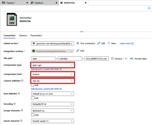
Figure 4-28. Specifying file format settings for a VCF file connection
On the “Schema” tab, shown in Figure 4-29, click “Import Schema > From sample file” and upload the vcf_schema.tsv.gz file from the /04_data_orchestration folder in the supplementary materials. If you do not have access to this file (or want to customize the column names), simply create a tab-separated file with the VCF headers (as shown in the following code block) and gzip it. This will define the column names as the VCF file is read:
CHROM POS ID REF ALT QUAL FILTER INFO
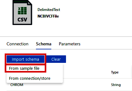
Figure 4-29. Specifying VCF file schema
Back over in the Data Flow tab, shown in Figure 4-30, click the “VCFSource” module and click the “Data preview” tab in the bottom part of the screen. Click the “Refresh” button. Once your debug session is ready, Data Factory will read in a sample of the VCF file and parse it according to your specifications. The “Data preview” tabs are very useful in understanding the state of the data at each step of the Data Flow.
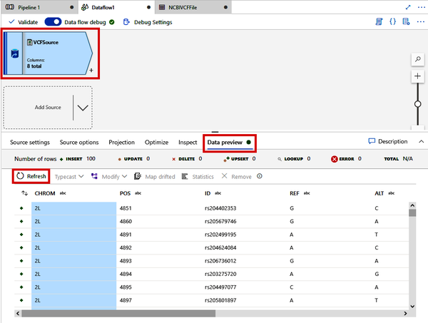
Figure 4-30. Previewing the VCF file parsing
Click the small + sign by the VCFSource module. Note that there are many different modules that we can use to join datasets together, change a dataset’s shape (Pivot, Unpivot, etc.), or change the contents of the data (Aggregate, Filter, etc.).
For this next step, we will parse the INFO column of the VCF data to create an array of values, which will make this flexible column of information more useful later. From the + menu, click “Derived Column,” as shown in Figure 4-31.
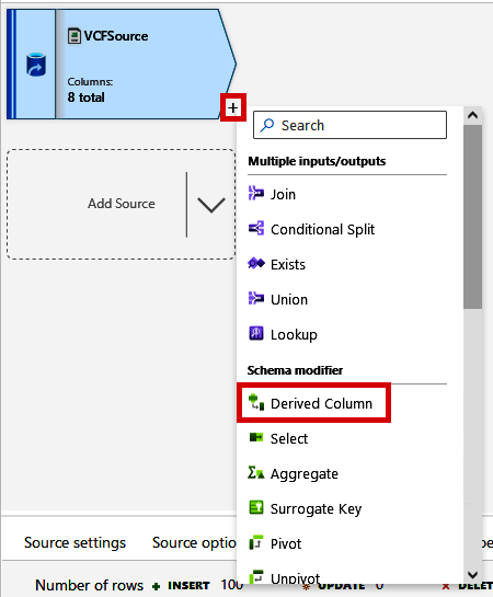
Figure 4-31. Adding a Derived Column module
As shown in Figure 4-32, click the new Derived Column module that gets created and change the Output stream name to “SplitINFOColumn.” Click the “+ Add” button and select the INFO column from the drop-down box. For the expression, you can use the expression builder, which will help you see all of the functions and their documentation. For now, you can simply paste in split(INFO, ";").
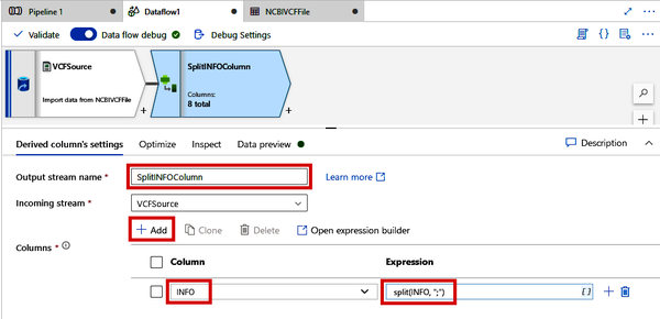
Figure 4-32. Splitting the INFO column of a VCF file using the Derived Column module
Once you have specified how the INFO column should be split, you can view the output of this process under the “Data preview” tab, shown in Figure 4-33. Note how the INFO column is now a column of arrays rather than long strings. Later, this will be useful for when we need to pull specific information out of this column.
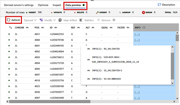
Figure 4-33. Previewing the split INFO column as an array
Finally, we need to write this data back to our data lake but as a different file format. Click the small + button beside your SplitINFOColumn module and select the “Sink” option. See Figure 4-34. This will add a Sink module, which basically allows us to write out data to a destination.
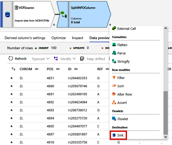
Figure 4-34. Adding a Sink module
In the Sink module that gets created, change the “Output stream name” to “ParquetOutput.” We have not yet defined our destination, so click the “+ New” button next to “Dataset.” Click the “Azure Data Lake Storage Gen2” option and click the “Continue” button (the same as in Figure 4-24). This time, though, select the Parquet option on the “Select format” screen and click the “Continue” button. See Figure 4-35.
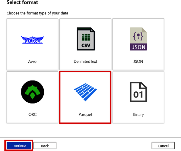
Figure 4-35. Selecting the Parquet format as the Sink data type
On the Set properties screen, shown in Figure 4-36, change the “Name” to “NCBIParquetFile” and use the same “Linked service” you used in Figure 4-26. Use the same file path from before as well, except leave the specific filename blank (as shown in Figure 4-36) and click the “OK” button.
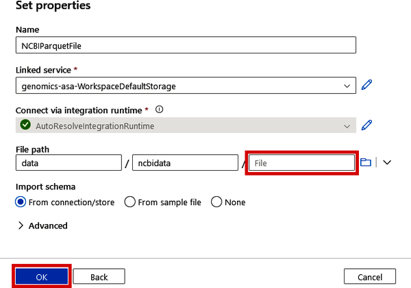
Figure 4-36. Specifying the Sink location of the output Parquet file
At this point, you should have a simple Data Flow of three steps: 1) read data from the VCF file; 2) split the INFO column into an array; and 3) write the data out as a Parquet file, similar to what is shown in Figure 4-37. Click the “Properties” button on the top right and rename your Data Flow to “VCF Parsing Data flow.” After this, navigate back to your main Pipeline tab (likely called “Pipeline 1”).

Figure 4-37. VCF Parsing Data Flow
Click the “Properties” button for the pipeline and rename it to “VCF Parsing Pipeline.” In addition, ensure the Data Flow selected under the Settings tab is the “VCF Parsing Data flow” we just created. See Figure 4-38.
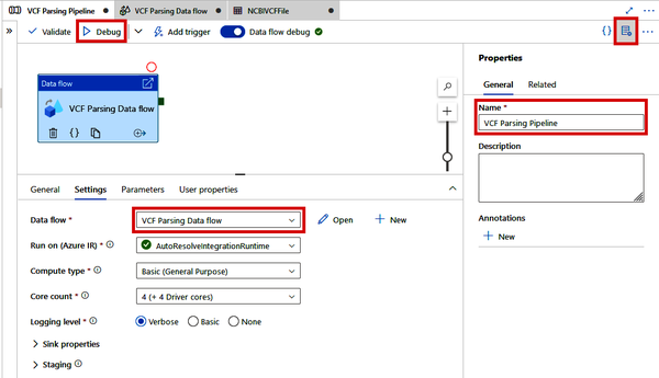
Figure 4-38. VCF Parsing pipeline
Ready to give it a spin? Click the “Debug” button at the top of the screen, which will run the pipeline (which will execute the Data Flow) and create a Parquet file of the NCBI VCF data in your data lake. If you see the green check mark (shown in Figure 4-39) on the Data flow module and in the Output tab, success!
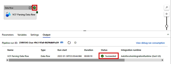
Figure 4-39. Successful pipeline debug run
Now you can go back to the Azure Portal and check in your data lake to see the Parquet file that was just created. See Figure 4-40.
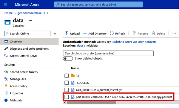
Figure 4-40. Locating the Parquet file of the NCBI VCF data
One final, very important thing. Before you close out of Data Factory, make sure to always click the “Publish all” button at the top of the screen, shown in Figure 4-41. This will save any datasets, pipelines, or Data Flows that you have created.

Figure 4-41. Locating the “Publish all” button in Data Factory
In this section, we’ve shown how to use the power of Data Flows to perform complex parsing on nonstandard file formats like VCF. This functionality is really important when we need to get our esoteric bioinformatics file formats to play well with enterprise data tools. Note that there is a ton of other Data Flow capabilities that we haven’t covered in this book, but I encourage you to explore Data Flows with other human-readable file types such as SAM, GFF, and more to see if you can convert those files into other formats as we did here with a VCF file.
Building and Triggering Pipelines for Automation
As powerful and useful as a Data Flow in Data Factory is at transforming data, it does have its limits. Other services in Azure may be better suited for larger or more specialized transformation tasks. For such tasks, we can simply use Data Factory to farm out this processing to other services such as Databricks.
In addition to orchestrating data operations on external services (such as pulling sequence data from an NGS vendor’s FTP site), we can trigger such actions to kick off Pipelines based on certain conditions. For example, we can schedule a pipeline to run every day at 8 a.m., or we can kick off the pipeline anytime new data with a certain file extension is added to a particular directory.
In fact, we’ll be creating a Databricks-based VCF conversion pipeline in the section “Orchestrating a Databricks Notebook from Data Factory” in Chapter 5.
In this chapter, we’ve covered the basics of cloud-based data orchestration using Data Factory. As you can see, Data Factory is a fairly versatile tool for copying or moving data into Azure from external services (using Pipelines) or orchestrating the transformation of data, by using either Data Flows or other Azure-based services like Databricks. In summary, data orchestration is important in that it enables us to get data into the cloud and interact with other cloud-based data services. Azure Data Factory provides an interactive interface to create pipelines and copy data from source to destination (sink) and call other services.
Within Azure Data Factory, Data Flows are useful for transforming data in Pipelines, providing a single place to both orchestrate tasks and manipulate data. Plus, with triggers, any pipeline can be scheduled to run on a standard interval or triggered based on an event. Event-based triggers are useful for kicking off pipelines when new data becomes available.
In the next chapter, we’ll be covering compute services that allow you to scale all sorts of data processing from bioinformatics pipelines to machine learning and beyond. Many of the services we cover in the next chapter can also be called from Data Factory, which will help you further automate and scale your data processing needs.
Get Genomics in the Azure Cloud now with the O’Reilly learning platform.
O’Reilly members experience books, live events, courses curated by job role, and more from O’Reilly and nearly 200 top publishers.

