17Transmission Lines
17.1 Transient Analysis
In the previous chapter we reviewed static electric fields due to stationary charge distributions, and static magnetic fields, due to the charges moving at constant speed, i.e. dc currents.
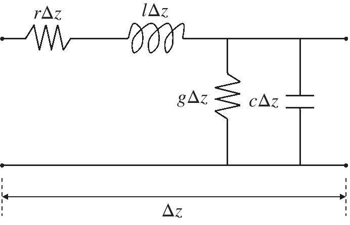
A transmission line can be modeled as a distributed parameter circuit consisting a series of small segments of length Δz, as shown in Figure 17.1

Figure 17.1 Circuit model of a transmission line.
The distributed parameters describing the transmission line are:
- r – resistance per‐unit‐length (Ω/m)
- l – inductance per‐unit‐length (H/m)
- g – conductance per‐unit‐length (S/m)
- c – capacitance per‐unit‐length (F/m)
The transmission line model in Figure 17.1 describes a lossy transmission line. To gain an insight into transmission line theory it is very helpful to consider a lossless transmission line first. Such a transmission line is shown in Figure 17.2.

Figure 17.2 Circuit model of a lossless transmission line.
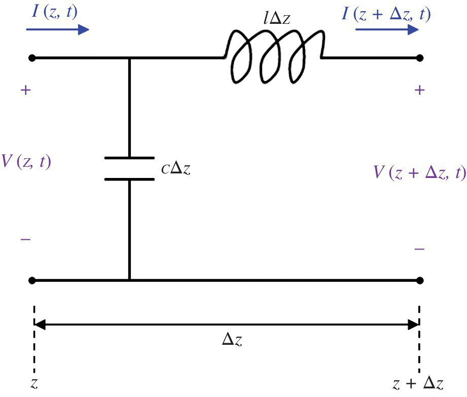
To obtain the transmission line equations let’s consider a single segment of a lossless transmission line shown in Figure 17.3.

Figure 17.3 Single segment of a lossless transmission line.
Writing Kirchhoff’s voltage law around the outside loop results in
or
Get Foundations of Electromagnetic Compatibility with Practical Applications now with the O’Reilly learning platform.
O’Reilly members experience books, live events, courses curated by job role, and more from O’Reilly and nearly 200 top publishers.

