Appendix F
Decision-Point Control
The location of the decision point (the intersection of the decision threshold with the sampling instant) in the eye diagram has a significant impact on the bit-error rate (BER) of the receiver. In the following, we discuss a method to control the decision point based on pseudo-error measurements.
Decision-Threshold Control
The optimum decision threshold (a.k.a. slice level) is at the point where the probability distributions of the zero and the one bits intersect (cf. Figs 4.4 and 4.5). If the noise distributions have equal widths (same rms value), the optimum decision threshold is centered halfway between the zero and one levels. An AC-coupled receiver automatically slices at that threshold level, given a DC-balanced NRZ signal and no circuit offsets. However, if there is more noise on the ones than the zeros, for example, because optical amplifiers or an APD is used, the optimum decision threshold is below the center (see Fig. F.1) and a simple AC-coupled receiver makes more errors than necessary. [![]() Problem F.1.]
Problem F.1.]
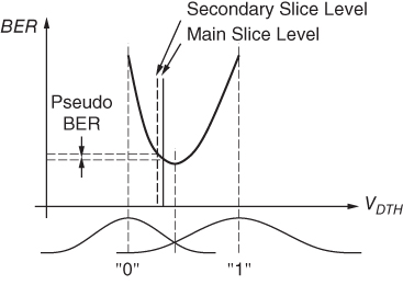
Figure F.1 Optimum decision threshold for unequal noise distributions.
Making the decision threshold adjustable and setting it for the lowest BER avoids this performance penalty [1]. An intentional offset voltage in the decision ...
Get Analysis and Design of Transimpedance Amplifiers for Optical Receivers now with the O’Reilly learning platform.
O’Reilly members experience books, live events, courses curated by job role, and more from O’Reilly and nearly 200 top publishers.

